Sony dps r 7 service manual

This is the 85 pages manual for sony dps r 7 service manual.
Read or download the pdf for free. If you want to contribute, please mail your pdfs to info@audioservicemanuals.com.

Page: 1 / 85
left right
sony dps r 7 service manual

Extracted text from sony dps r 7 service manual (Ocr-read)


Page 1

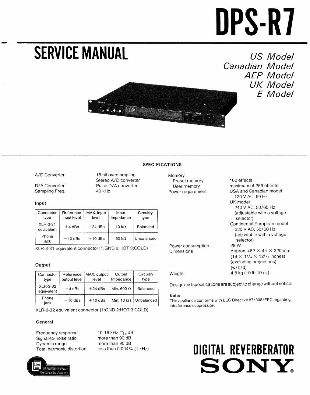
DPS-R7

SERVICE MANUAL us Model

Canadian Model
AEP Model
UK Model
E Model

SPECIFICATlONS

A/D Converter 18 bit oversampling Memory
Stereo A/D converter Preset memory 100 elfects
D/A Converter Pulse D/A converter User memory maximum of 256 effects
Sampling Freq. 40 kHz Power requirement USA and Canadian model
120 V AC, 60 HZ
Input UK model
240 V AC, 50/60 Hz
Connector Reference MAX input input Circuitry (adjustable with a voltage
type input level level Impedance type selector)
XLR-3-31 Continental European model
. + 4
equrvalent st +24 st 10 kt) Balanced 230 V AC. 50/60 HZ
Phone (adjustable with a voltage
jack w 10 st +10 st 50 km Unbalanced selector)
- t . t Power consumption 28 W
XLR 3 81 equrvalentconnector (ttGND 2,HOT 3.COLD) Dimensions Approx 482 X 44 X 320 mm
(19 X13/A >< 125/3 inches)
(excluding projections)
out (w/h/d)
Connector Relerence MAXi output Output Circuitry Weight 48 k9 (10 lb 10 OZ)
type output level level impedance type
XLR-s-az Design and specifications are subject to change without notice,
. +4 dss +24 st Min. 600 n Balanced
equivalent
Phone Note:
jack _10 st +10 dBS M'- 10 k Unbalanced This appliance conforms with EEC Directive 87/308/EEC regarding

interlerence suppression.

XLR-3-32 equivalent connector (1 :GND 2:HOT 3:COLD)

General

Frequency response
Signal-to-noise ratio
Dynamic range

10-18 kHz :QodB
more than 90 dB
more than 90 dB

Total harmonic distortion less than 0004% (1 kHz) DIGITAL REVERBERAT" R

SONY;

Page 2

DPS-R7

TABLE OF CONTENTS

Section Title Page
Specification ....................................................................... 1
1' GENERAL ........................................................ . .......... 3
2 LIST OF IC TERMINALS-
3~ DISASSEMBLY ............................... . ......................... 11
4. ADJUSTMENT ........................................... . ............ 11
5. DIAGRAMS
Block Diagram .................................................. 12
Printed Wiring Boardsm '16
Schematic Diagram (1) ~19
Schematic Diagram (2)~~ .23
IC Block Diagrams ~~~~~~~~~~~~~~~~~~~~~~~~~~~~~~~~~~~~~~~~~~~~ 27
6. EXPLODED VIEW ~~~~~~~~~~~~~~~~~~~~~~~~~~~~~~~~~~~~~~~~~~~~~~~~~~ 30
7 ELECTRICAL PARTS LIST ~ ~32

SAFETY-RELATED COMPONENT WARNINGII

COMPONENTS IDENTIFIED BY MARK A OR DOTTED
LINE WITH MARK A ON THE SCHEMATIC DIAGRAMS
AND IN THE PARTS LIST ARE CRITICAL TO SAFE
OPERATION. REPLACE THESE COMPONENTS WITH
SONY PARTS WHOSE PART NUMBERS APPEAR AS
SHOWN IN THIS MANUAL OR IN SUPPLEMENTS PUB-
LISHED BY SONY.

ATTENTION AU COMPOSANT AYANT RAPPORT
A LA SECURITEI

LES COMPOSANTS IDENTIFIES PAR UNE MAROUE A
SUR LES DIAGRAMMES SCHEMATIOUES ET LA LISTE
DES PIECES SONT CRITIQUES POUR LA SECURITE
DE FONCTIONNEMENT. NE REMPLACER CES COM-
POSANTS QUE PAR DES PIECES SONY DONT LES
NUMEROS SONT DONNES DANS CE MANUEL 0U
DANS LES SUPPLEMENTS PUBLIES PAR SONY.