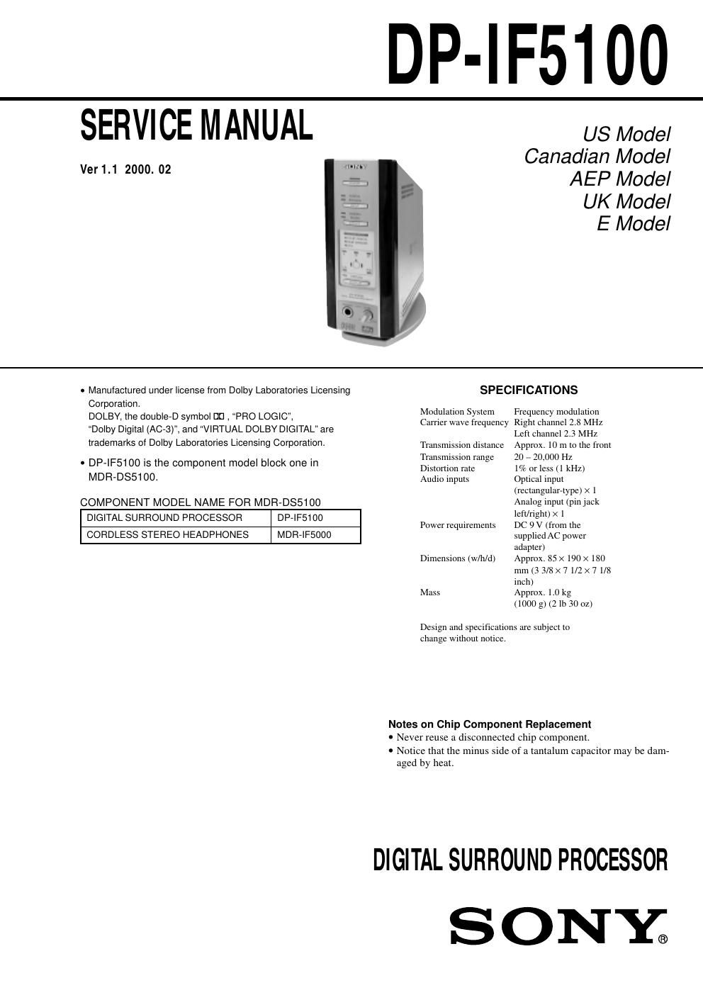
Sony dpif 5100 service manual

This is the 34 pages manual for sony dpif 5100 service manual.
Read or download the pdf for free. If you want to contribute, please mail your pdfs to info@audioservicemanuals.com.

Page: 1 / 34
left right
sony dpif 5100 service manual

Extracted text from sony dpif 5100 service manual (Ocr-read)


Page 1

-“ 2 -“ TABLE OF CONTENTS 1. GENERAL Location and Function of Parts ............................................... 3 Listening to the Sound of the Connected Component ............ 3 2. DISASSEMBLY 2-1. Cover Assy .......................................................................... 5 2-2. Panel Assy, Front ................................................................. 5 2-3. Panel Assy, Sub ................................................................... 6 2-4. TX Board ............................................................................ 6 3. SERVICE MODE 3-1. General ................................................................................ 7 3-2. Setting the Test Mode .......................................................... 7 3-3. Releasing the Test Mode ..................................................... 7 3-4. Test Mode ............................................................................ 7 4. ELECTRICAL ADJUSTMENTS ................................... 8 5. DIAGRAMS 5-1. IC Pin Descriptions ............................................................. 9 5-1-1. IC201 µPD784216 (Program, System Control) ............ 9 5-1-2. IC301 CXD9511AQ (Dolby Digital (AC-3)/ Pro Logic, DTS Decoder) ............................................ 11 5-1-3. IC302 XCB56362PV100 (24 Bit Audio Digital Signal Processor) ......................................................... 13 5-2. Block Diagrams ................................................................ 17 5-2-1. Block Diagram -“Processor Section-“ ........................... 17 5-2-2. Block Diagram -“Transmitter Section-“ ........................ 19 5-3. Printed Wiring Boards and Schematic Diagrams .............. 21 5-3-1. Printed Wiring Board -“TX Board-“ ............................. 21 5-3-2. Schematic Diagram -“TX Board (1/2)-“ ....................... 25 5-3-3. Schematic Diagram -“TX Board (2/2)-“ ....................... 27 5-3-4. Printed Wiring Board -“LED Board-“ ........................... 29 5-3-5. Schematic Diagram -“LED Board-“ .............................. 31 5-3-6. Printed Wiring Board -“AMP Board-“ .......................... 33 5-3-7. Schematic Diagram -“AMP Board-“ ............................. 34 5-4. IC Block Diagrams ........................................................... 35 6. EXPLODED VIEW ........................................................... 38 7. ELECTRICAL PARTS LIST ......................................... 39

Page 2

-“ 3 -“ SECTION 1 GENERAL This section is extracted from instruction manual.