Sony dpif 3000 service manual

This is the 28 pages manual for sony dpif 3000 service manual.
Read or download the pdf for free. If you want to contribute, please mail your pdfs to info@audioservicemanuals.com.

Page: 1 / 28
left right
sony dpif 3000 service manual

Extracted text from sony dpif 3000 service manual (Ocr-read)


Page 1

DP-IF3000

SERVICE MANUAL us Model

Canadian Model
AEP Model

UK Model

E Model

Tourist Model

Ver 1.1 2004. 02

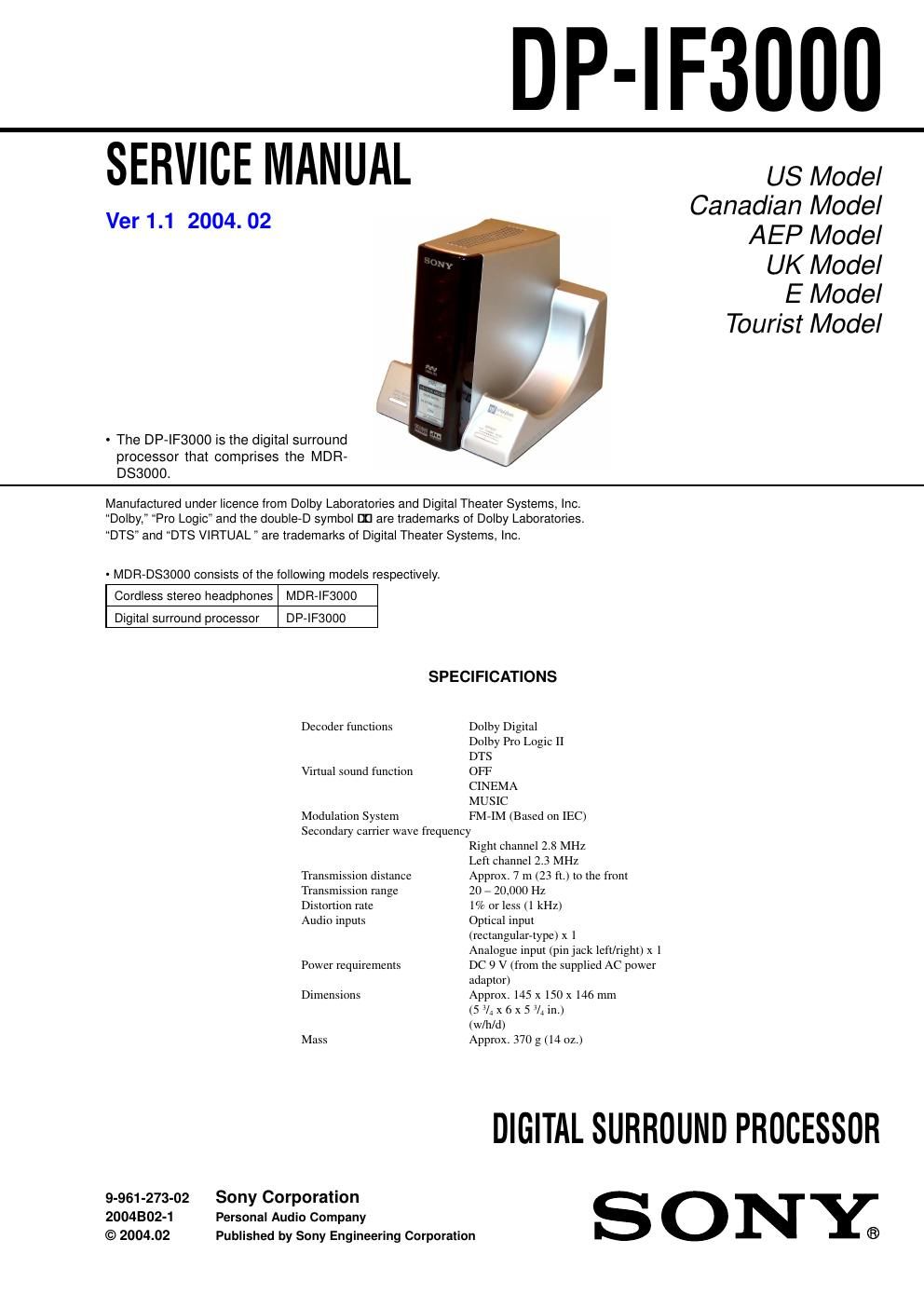
- The DP-IF3000 is the digital surround
processor that comprises the MDFt-
DS3000.

Manufactured under licence from Dolby Laboratories and Digital Theater Systems, Inc.
Dolby," Pro Logic" and the double-D symbol in are trademarks of Dolby Laboratories.
DTS" and DTS VIRTUAL " are trademarks of Digital Theater Systems, Inc.

- MDR-DSBOOO consists of the lollowing models respectively.
Cordless stereo headphones MDR-IF3000
Digital surround processor DP-IF3000

SPECIFICATIONS

Decoder functions Dolby Digital
Dolby Pro Logic II
DTS
Virtual sound function OFF
CINEMA
MUSIC
Modulation System FM-IM (Based on IEC)
Secondary carrier wave frequency
Right channel 2.8 MHZ
Left channel 2.3 MHz

Transm' ion distance Approx. 7 m (23 ft.) to the front
Transmission range 20 - 20,000 Hz

Distortion rate 1% or less (1 kHz)

Audio inputs Optical input

(rectangular-type) x l
Analogue input (pinjack left/right) x 1

Power requirements DC 9 V (from the supplied AC power
adaptor)

Dimensions Approx. 145 x 150 x 146 mm
(5 V; x 6 x 5 V, in.)
(w/h/d)

Mass Approx. 370 g (14 oz.)

DIGITAL SURROUND PROCESSOR
9-961-273-02 Sony Corporation S O N Y
2004802-1 Personal Audio Company
© 2004.02 Published by Sony Engineering Corporation ®

Page 2

DP-I F3000

Notes on Chip Component Replacement

' Never reuse a disconnected chip component.

' Notice that the minus side of a tantalum capacitor may be
damaged by heat.

0 UNLEADED SOLDER
Boards requiring use of unleaded solder are printed with the lead-
free mark (LF) indicating the solder contains no lead
(Caution: Some printed circuit boards may not come printed with
the lead free mark due to their particular size.)

I

LEAD FREE MARK

Unleaded solder has the following characteristics.

0 Unleaded solder melts at a temperature about 40°C higher than
ordinary solder.
Ordinary soldering irons can be used but the iron tip has to be
applied to the solder joint for a slightly longer time.
Soldering irons using a temperature regulator should be set to
about 350°C.
Caution: The printed pattern (copper foil) may peel away if
the heated tip is applied for too long, so be careful!

- Strong viscosity
Unleaded solder is more viscous (sticky, less prone to flow)
than ordinary solder so use caution not to let solder bridges
occur such as on IC pins, etc.

- Usable with ordinary solder
It is best to use only unleaded solder but unleaded solder may
also be added to ordinary solder.

0 Repair DP»IF3000 with MDR-IFSOOO.

TABLE OF CONTENTS

1. GENERAL

2. DISASSEMBLY
2-1. Cabinet (Lower) Assy, Luminous Window Ass

IF Board ............. 5

2-2. Digital Board ........................................................................ 6
3. ELECTRICAL ADJUSTMENTS

Oscillation Frequency Adjustment .......................................... 7

RF Level Adjustment ............................................................... 7

4. DIAGRAMS
4-1. Block Diagrams ..........

.10

4-2. Printed Wiring Board ~ Digital Section (Side A) e

Printed Wiring Board -- Digital Section (Side B) - . 11
4-3. Schematic Diagram ~ Digital (1/2)Section -- ...... . 12
4-4. Schematic Diagram -- Digital (2/2)Section - . 13

4-5. Printed Wiring Board ~ IF Section » ........
4-6. Schematic Diagram ~ IF Section A
4-7. IC Pin Function Description
4-8. IC Block Diagram

5. EXPLODED VIEW

5-1. Processor Section 21

6. ELECTRICAL PARTS LIST ......................................... 22