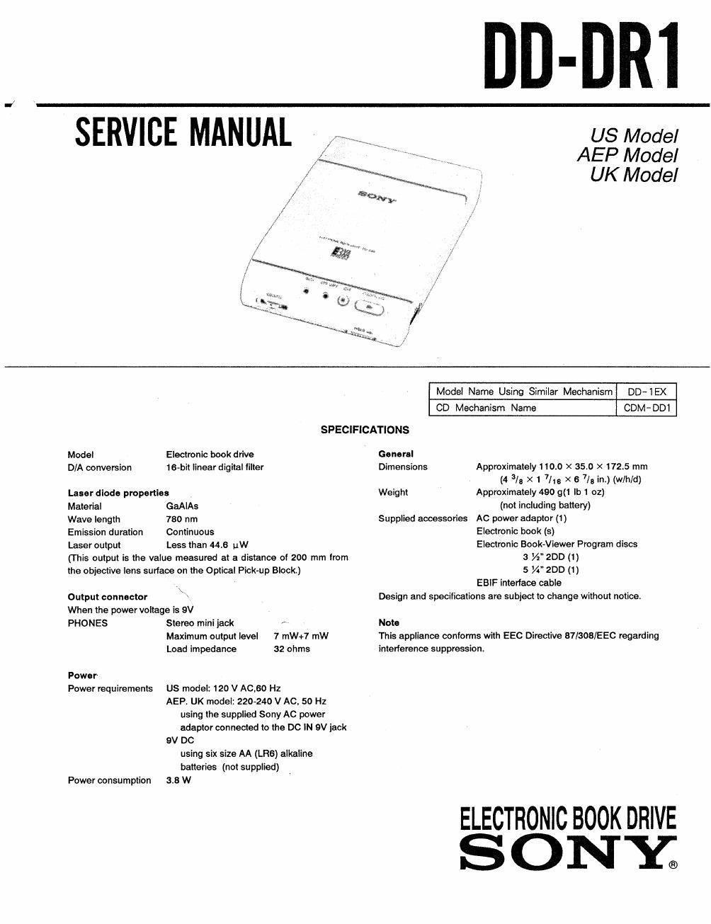
Sony dd dr 1 service manual

This is the 30 pages manual for sony dd dr 1 service manual.
Read or download the pdf for free. If you want to contribute, please mail your pdfs to info@audioservicemanuals.com.

Page: 1 / 30
left right
sony dd dr 1 service manual

Extracted text from sony dd dr 1 service manual (Ocr-read)


Page 1

__ DD-DRl

US Model
AEP Model
W UK Model

SPECIFICATIONS
Model Electronic book drive General
D/A conversion 16-bit linear digital filter Dimensions
Laser diode propertles Weight

Material GaAIAs

Wave length 730 nm

Emission duration Continuous

Laser output Less than 445 uW

(This output is the value measured at a distance of 200 mm from
the objective lens surface on the Optical Pick-up Block.)

Output connector \ \

When the power voltage is 9V

PHONES Stereo mini jack r
Maximum output level 7 mW+7 mW
Load impedance 32 ohms

Power

Power requirements US model: 120 V AC,60 Hz

AEP. UK model: 220-240 V AC, 50 Hz
using the supplied Sony AC power
adaptor connected to the DC IN 9V jack

9V DC
using six size AA (LRS) alkaline
batteries (not supplied)

Power consumption 3.8 W

Supplied accessories

Model Name Using Similar Mechanism

DD- 1 EX

CD Mechanism Name

CDM-DDl

Approximately 110.0 X 3510 x 172.5 mm
(4 3/8 X 1 7/13 X 6 7/3 in.) (w/h/d)

Approximately 490 9(1 lb 1 02)

(not including battery)
AC power adapter (1)
Electronic book (5)

Electronic Book-Viewer Program discs

3 W200 (1)
5 W 200 (1)
EBIF interface cable

Design and specifications are subject to change without notice

Note

This appliance conforms with EEC Directive 87/308lEEC regarding
interference suppression.

ELECTRONIC BOOK DRIVE
ONYg

Page 2

DD- DR1

TABLE OF CONTENTS

Section Title Pa
Specifications ............... . . . .. .................. . . . 1
LSERVICINGNOTES .................. 000090-009» ..... 2
2_GENERAL ..... coccoc-cvc ................ ...........4
3. DISASSEMBLY ......... . . ........................... 5
4.ELECTHICA|_ ADJUSTMENTS ..... H... . . . .. ......... 7
5. DIAGRAMS

5- 1. 1C Description ...................... 10

5»2, Block Diagrams ........... . . . . . . . . . . .......... 17

5-3. Semiconductor Lead Layouts --------------- ' 20

5-4. Primed Wiring Board- . . . . . . . . ................ 21

5-5. Schematic Diagram 25

5-6. IC Block Diagrams. .
5- 7. Waveforms . . . . . . .......

s. EXPLODED VIEWS ~~~~~~~~~~~~~~~~~~~~~~~~~~~~~~~ 33

7. ELECTRICAL PARTS LIST - ~ ~
HARDWARE LIST ~~~~~~~~~~~

........... ..... 36
..... ............ 4o

For the Customers In AEP model.

This electronic book drive is
classified as a CLASS 1 LASER
product.

The CLASS 1 LASER PRODUCT
label is located on the bottom
exterior.

CLASS I LASER PRODUCT

LUOKAN 1 LASERLAITE
KLASS 1 LASERAPPAT

SECTION 1
SERVICING NOTES

NOTES ON HANDLING THE OPTICAL PICK-UP BLOCK
OR BASE UNIT

The laser diode in the optical pick-up block may suffer
electrostatic breakdown because of the potential difference
generated by the charged electrostatic load, etc on clothing
and the human body.

During repair, pay attention to electrostatic breakdown and
also use the procedure in the printed matter which is
included in the repair parts

The flexible board is easily damaged and should be handled
with care.

Flexible clrcult Board Repalrlng

° Keep the temperature of the soldering iron around
270°C during repairing.

' Do not touch the soldering iron on the same conductor
of the circuit board (within 3 times).

° Be careful not to apply force on the conductor when
soldering or unsoldering.

Notes on chip component replacement

' Never reuse a disconnected chip component.

0 Notice that the minus side of a tantalum capacitor may
be damaged by heat.

Before Replaclng the Optlcal Block

Please be sure to check thoroughly the parameters as for
the Optical Block Checking Procedures (Part No. :9-960-
OZ7~ll) issued separately before replacing the optical block.
Note and specifications required to check are given below.

- FOK output: IC501©pin
When checking FOK, unsolder bridge between IC501 @pin
(FE) and R553.

~ S carve P-to-P value: 2.95 Vp-p

. Adjusted part for focus gain adjustment: RV503

- RF signal P-to-P value: 0.75-1.41 Vp-p

- Traverse signal P-to-P value: 1.8Vp-p

- The repairing grating holder is impossible.

0 Adjusted part for tracking gain adjustment: RV504

_2_