Sony dd 10 bz service manual

This is the 55 pages manual for sony dd 10 bz service manual.
Read or download the pdf for free. If you want to contribute, please mail your pdfs to info@audioservicemanuals.com.

Page: 1 / 55
left right
sony dd 10 bz service manual

Extracted text from sony dd 10 bz service manual (Ocr-read)


Page 1

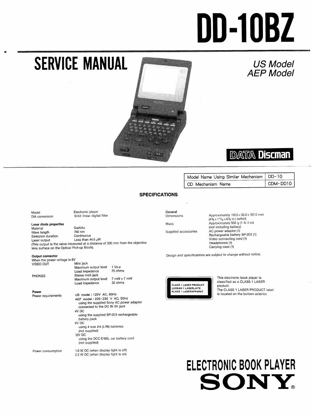
DD-lUBZ

US Model
AEP Model

@ATA Discman

Model Name Using Similar Mechanism DD-lO

CD Mechanism Name CDM- D01 0
SPECIFICATIONS
Model Electronic player General
DlA conversion 16bit Ilnear digital tiller Dimensions Approximately 110.0 x 35.0 x 157.0 mm
(Max 1"Asx63/a in.) (th/dl
Laser diode properties Mass Approximately 550 g (1 lb 3 02)
Material GaAIAs (not including battery)
Wave length 780 nm Supplied accessories AC power adapter (1)
Emission duration Continuous Rechargeable battery any (1)
Laser output Less than 44-6 uW Video connecting cord (1)
(rhis output is the value measured at a distance oi 200 mm from the obiective Headphones (1)
lens surtaoe on the Optical Pick-up Block). Carrying case (1)
WW" connector Design and specifications are subject to change without notice.
When the power voltage ls 6V
VlDEO OUT Mini jack
Maximum output level 1 Vp-p
Load impedance 75 ohms
PHONES Stereo mini jack
Maximum output level 7 mw+7 mw This electronic book player is
Load impedance 32 ohms classified as a CLASS 1 LASER
5:333:23?
pm mss 5mg? The CLASS 1 LASER PRODUCT label
Power requirements US model 1 120V AC, 60H! is located on the bottom exterior.

AEP model : 220-230 V AC, SOHI
using the supplled Sony AC power adaptor
connected to the DC lN 6V lack

4V DC
using the supplied BP<2EX rechargeable
battery pack

6V DC
using 4 size AA (LBS) batteries
(not supplied)

12V DC
using the DCCeEtSOL car battery Cord
(not supplied)

Power consumption 16 W DC (when display light is oil)
2.2 W DC (when display lighl is on)

ELECTRONIC BOOK PLAYER
ONE

Page 2

DD-1OBZ

TABLE OF CONTENTS

Section Title

F:
n)
(v

1. SERVICING NOTES - ~

2 GENERAL ......................................... 11
3_ DISASSEMBLY .................................... 24
4. ELECTRICAL ADJUSTMENTS ....................... 26
5. DIAGRAMS

5- 1. Block Diagram ----------

5-2. Printed Wiring Boards
5-3, Schematic Diagram -----
5-4. Semiconductor Lead Layouts ~~~~~~~~~~~~~~~ 44
5-5. Waveforms ------
5-6. IC Descriotions--
5-7. IC Block Diagrams"

56

6. EXPLODED VIEWS
6- 1. LCD Section
6-2. Cabinet Section - - -


~59

6-3. Mechanism Section (CDM-DDIO) ~~~~~~~~~~~ 60
7. ELECTRICAL PARTS 31- ........................ 61
HARDWARE LIST ................................. 67

SAFETY-RELATED COMPONENT WARNINGII

COMPONENTS IDENTIFIED BY MARK A OR DOTTED
LINE WITH MARK A ON THE SCHEMATIC DIAGRAMS
AND IN THE PARTS LIST ARE CRITICAL TO SAFE
OPERATION. REPLACE THESE COMPONENTS WITH
SONY PARTS WHOSE PART NUMBERS APPEAR AS
SHOWN IN THIS MANUAL OR IN SUPPLEMENTS PUB-
LISHED BY SONY.