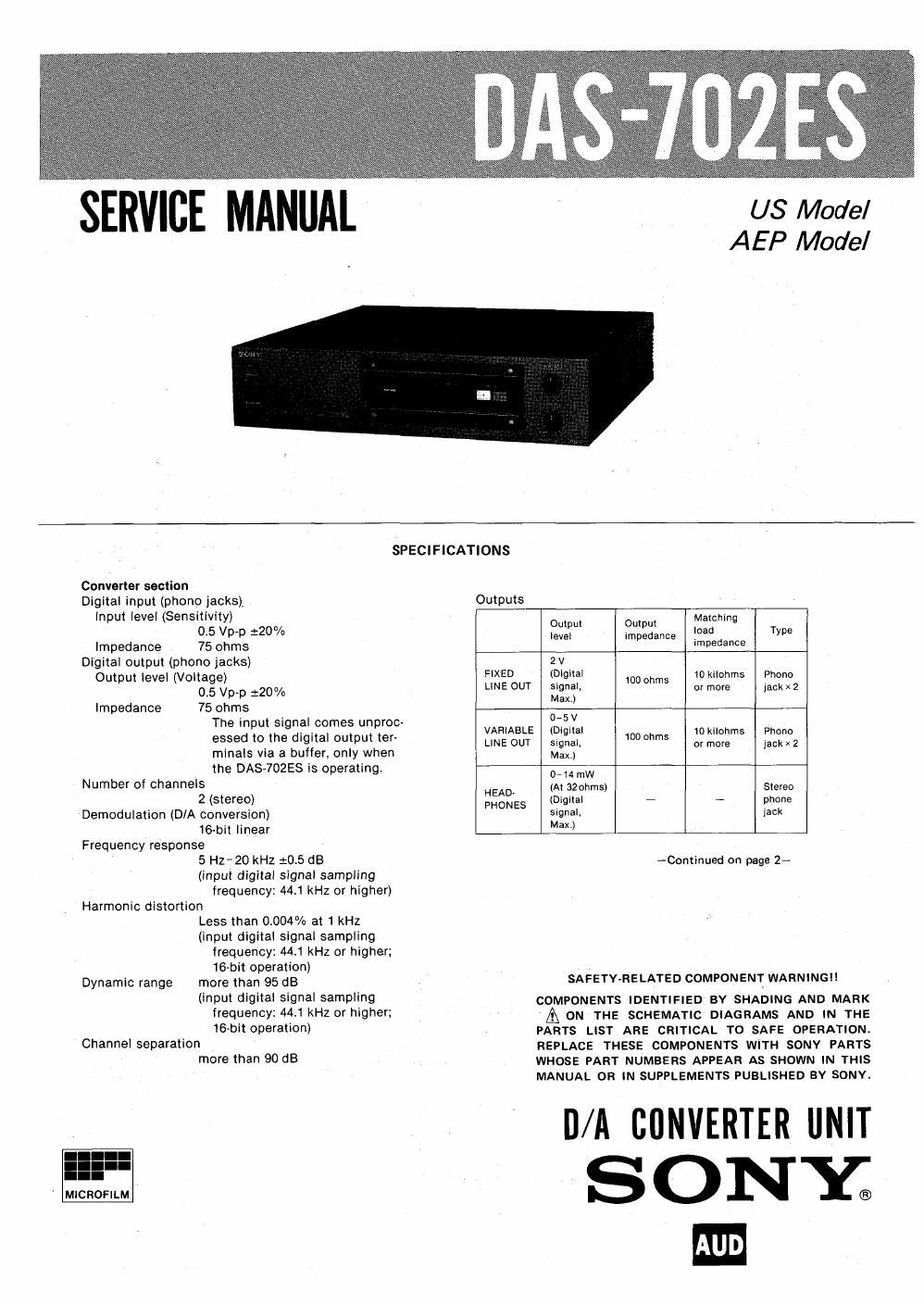
Sony das 702 es service manual

This is the 30 pages manual for sony das 702 es service manual.
Read or download the pdf for free. If you want to contribute, please mail your pdfs to info@audioservicemanuals.com.

Page: 1 / 30
left right
sony das 702 es service manual

Extracted text from sony das 702 es service manual (Ocr-read)


Page 1

SERVICE MANUAL

US Model
AE P Model

SPECIFICATIONS

Convener section
Digital input (phono jacks),
input level (Sensitivity)
0.5 Vp~p 220%
Impedance 75 ohms
Digital output (phono jacks)
Output level (Voltage)
0.5 Vp-p 120%
Impedance 75 ohms
The input signal comes unproc-
essed to the digital output ter-
minals via a buffer, only when
the DAS-702ES is operating.
Number of channels
2 (stereo)
Demodulation (DIA conversion)
16-bit linear
Frequency response
5 H2-20 kHz :0.5 (13
(input digital signal sampling
frequency: 441 kHz or higher)
Harmonic distortion
Less than 0.004% at 1 kHz
(input digital signal sampling
frequency: 44.1 kHz or higher;
16-bit operation)
Dynamic range more than 95 dB
(input digital signal sampling
frequency: 44.1 kHz or higher;
16-bit operation)
Channel separation
more than 90 dB

Ml

I. p
CROFILM

Outputs
Output Output IMBLChing T
level Impedance .°a 9
Impedance
2 v
FIXED (Digital 10 kilohms Phone
LINE our signal, 1° 5 or more jack x 2
Max.)
0-5 v
VARIABLE (Digital 10 kilohms Phono
LINE OUT signal, 10° °th or more jack x 2
Max.)
0- 14 mW
HEAD (Si :IZIWMS) Stereo
PHONES I 9 T p 9
Signal. )ack
Max.)

~Continued on page 2-

SAFETY-RELATED COMPONENT WARNING

COMPONENTS IDENTIFIED BY SHADING AND MARK

& ON THE SCHEMATIC DIAGRAMS AND IN THE
PARTS LIST ARE CRITICAL TO SAFE OPERATION.
REPLACE THESE COMPONENTS WITH SONY PARTS
WHOSE PART NUMBERS APPEAR AS SHOWN IN THIS
MANUAL OR IN SUPPLEMENTS PUBLISHED BY SONY.

D/A CONVERTER UNIT
SONY;

Page 2

Bissau;

General
System *D/A Converter
Power requirements
U.S.A. model: 120 V ac, 60 Hz
AEP model: 220-240 V ac,
50/60 Hz
Power consumption
U.S.A. model: 25 watts
AEP model: 28 watts

Dimensions Approx. 430 X 105 x 410 mm (w/hld)
(167/, x 4V. x 16% inches)
including projecting parts and
controls

Weight Approx. 11.5 kg (25 lbs 6 oz) net

Approx. 13.5 kg (29 lbs 13 oz) in
shipping carton

om-.- nvuu-ow-ov-o it»--- unoooaooo w- the... vow- wow ~o n . tr -o,»-n o.o w o n o no»--- '-m o. 9 i, -41 -ooa -1 o u»- m-.-

SAFETY CHECK-OUT (US Model)

After correcting the original service problem,
perform the following safety check before releasing
the set to the customer:

Check the antenna terminals, metal trim, metallized
knobs, screws, and all other exposed metal parts for
AC leakage. Check leakage as described below.

LEAKAGE TEST

The AC leakage from any exposed metal part to
earth ground and from all exposed metal parts to any
exposed metal part having a return to chassis, must
not exceed 0.5 mA (500 microampers). Leakage
current can be measured by any one of three
methods.

1. A commercial leakage tester, such as the
Simpson 229 or RCA WT-540A. Follow the
manufacturers instructions to use these instru~
'ments.

A battery-operated AC milliammeter. The Data
Precision 245 digital multimeter is suitable for
this job.

0 o t»- w. .o it o w o a o it- it»- w--- ,- w - i»- . o m- o it 0 .1.

MODEL IDENTIFICATION

- Specification Label -

Measuring the voltage drop across a resistor by
means of a VOM or battery-operated AC volt-
meter. The limit indication is 0.75 V, so
analog meters must have an accurate low
voltage scale. The Simpson 250 and Sariwa
SH-63Trd are examples of a passive VOM that
is suitable. Nearly all battery operated digital
multimeters that have a 2 V AC range are
suitable. (See Fig. A)

To Exposed Metal
Pans on Set

A C
voltmeter
lo. 75 v)

0. 75oF

i_,
g 1.5m /
L.

Earth Ground

Fig. A. Using an AC voltmeter to check AC leakage.

SONYG.

MODEL N0. DAS-702ES

D/A CONVERTER UNIT

moo--- s-.- in o in o WOOOOO- it - - vow- - o --.,-.. - a- 0

US model:
AEP model:

AC: 120V - 60 Hz 25W
AC: 220V-240V 50/60 Hz