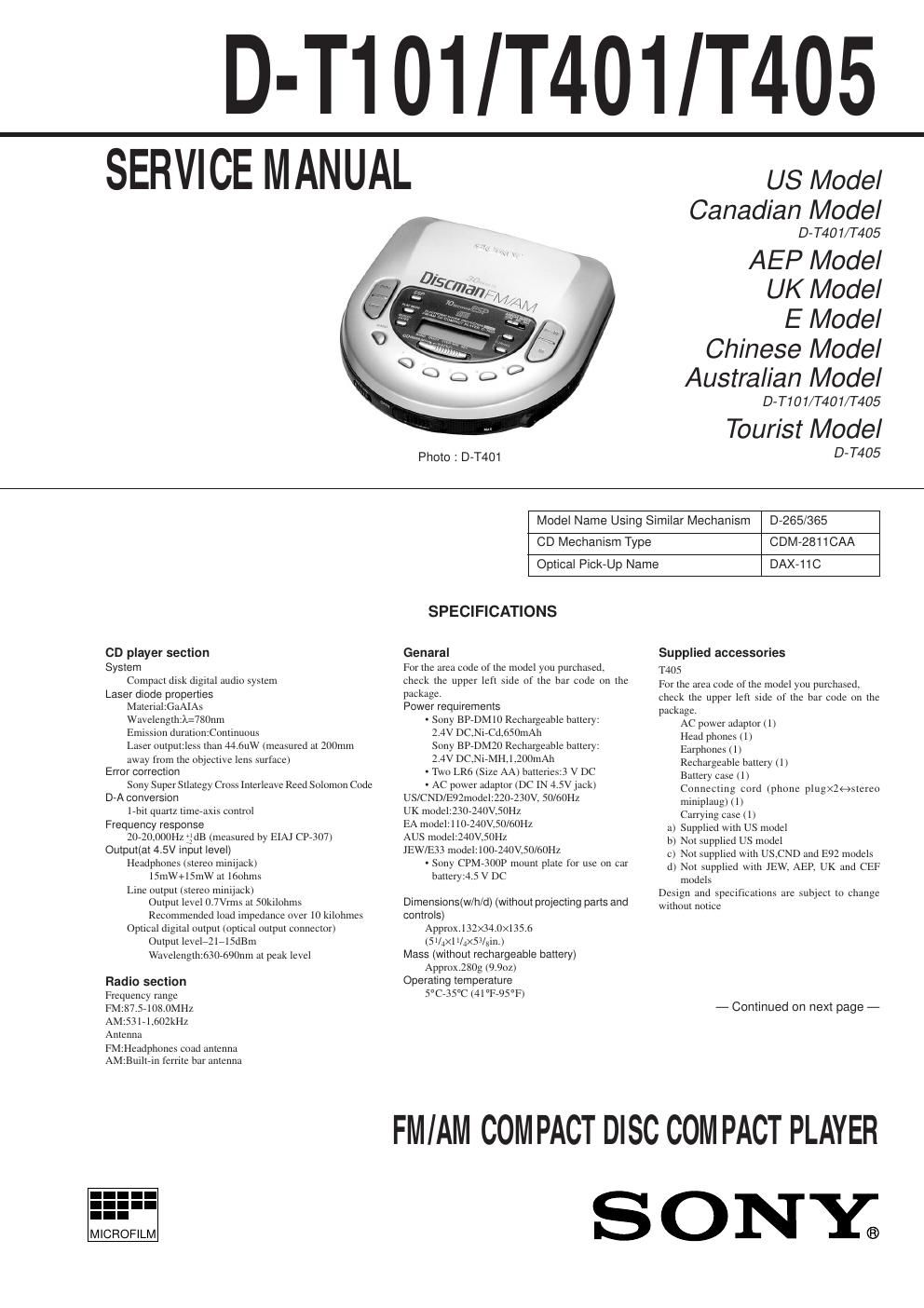
Sony d t 401 service manual

This is the 54 pages manual for sony d t 401 service manual.
Read or download the pdf for free. If you want to contribute, please mail your pdfs to info@audioservicemanuals.com.

Page: 1 / 54
left right
sony d t 401 service manual

Extracted text from sony d t 401 service manual (Ocr-read)


Page 1

Ñ 2 Ñ TABLE OF CONTENTS SAFETY-RELATED COMPONENT WARNING!! COMPONENTS IDENTIFIED BY MARK ! OR DOTTED LINE WITH MARK ! ON THE SCHEMATIC DIAGRAMS AND IN THE PARTS LIST ARE CRITICAL TO SAFE OPERATION. REPLACE THESE COMPONENTS WITH SONY PARTS WHOSE PART NUMBERS APPEAR AS SHOWN IN THIS MANUAL OR IN SUPPLEMENTS PUBLISHED BY SONY.ATTENTION AU COMPOSANT AYANT RAPPORT Ë LA SƒCURITƒ! LES COMPOSANTS IDENTIFƒS PAR UNE MARQUE ! SUR LES DIAGRAMMES SCHƒMATIQUES ET LA LISTE DES PIéCES SONT CRITIQUES POUR LA SƒCURITƒ DE FONCTIONNEMENT. NE REMPLACER CES COMPOSANTS QUE PAR DES PIéSES SONY DONT LES NUMƒROS SONT DONNƒS DANS CE MANUEL OU DANS LES SUPPƒMENTS PUBLIƒS PAR SONY. T101 Supplied accessories AC power adaptor(1) Earphones(1) Connecting cord(phone plugx2 stereo miniplug)(1) T401 AC power adaptor(1) Headphones(1) Earphones(1) Connecting cord(phone plugx2 stereo miniplug)(1) a)Supplied with US model b)Not supplied with US model c)Not supplied with AEP,UK and CEF models Recommended accessories Mount plate CPM-300P Mount kit CPM-450PC Mount kit CPM-300PC Car connecting pack CPA-9 Car battery cord with car connecting pack DCC-E26CP Car battery cord DCC-E245 Active speaker system SRS-A21,SRS-A41, SRS-A71 Rechargeable battery BP-DM10,BP-DM20 Connecting cord RK-G129HG Optical digital connecting cord POC-5B POC-10B,POC-15B,POC-5AB,POC-10AB,POC-15AB AC power adaptor AC-E45HG Stereo headphones MDR-35,MDR-E848 Sold in Japan only Your dealer may not handle some of the above listed accessories.Pleaseask the dealer for detailed information about the accessories in your country. NOTE: In this set, there are a former type (board suffix-12) and a new type (board suffix-13). In electrical adjustment, between a former type and a new type, there is a difference of measurement point. Flexible Circuit Board Repairing ¥ Keep the temperature of the soldering iron around 270°C during repairing. ¥ Do not touch the soldering iron on the same conductor of the circuit board (within 3 times). ¥ Be careful not to apply force on the conductor when soldering or unsoldering. Notes on chip component replacement ¥ Never reuse a disconnected chip component. ¥ Notice that the minus side of a tantalum capacitor may be damaged by heat. NOTES ON LASER DIODE EMISSION CHECK The laser beam on this model is concentrated so as to be focused on the disk reflective surface by the objective lens in the optical pick-up block. Therefore, when checking the laser diode emission, observe from more than 30cm away from the objective lens. 1. GENERAL ááááááááááááááááááááááááááááááááááááááááááááááááááá\ ááááááááááááááááááá 4 2. SERVICE NOTE ááááááááááááááááááááááááááááááááááááááááááááááááááá\ áááááááá 7 3. DISASSEMBLY 3-1. Cabinet (Lower) ááááááááááááááááááááááááááááááááááááááááááááááááááá\ áááááááááááááá 8 3-2. Cabinet (Upper) ááááááááááááááááááááááááááááááááááááááááááááááááááá\ ááááááááááááááá 8 3-3. Tuner Board ááááááááááááááááááááááááááááááááááááááááááááááááááá\ ááááááááááááááááááááá 9 3-4. CD Board ááááááááááááááááááááááááááááááááááááááááááááááááááá\ ááááááááááááááááááááááááá 9 4. SERVICE MODE ááááááááááááááááááááááááááááááááááááááááááááááááááá\ ááááá 10 5. ELECTRICAL ADJUSTMENT áááááááááááááááááááááááááááááá 11 6. DIAGRAMS 6-1. Block Diagram ÐCD SectionÐ áááááááááááááááááááááááááááááááááááááááááá 16 6-2. Block Diagram ÐTuner SectionÐ áááááááááááááááááááááááááááááááááááááá 19 6-3. Printed Wiring Board ÐTuner SectionÐ áááááááááááááááááááááááááááá 21 6-4. Schematic Diagram ÐTuner SectionÐ ááááááááááááááááááááááááááááááá 23 6-5. IC Block Diagrams ááááááááááááááááááááááááááááááááááááááááááááááááááá\ áááááááá 25 6-6. Printed Wiring Board ÐCD Section Ð ááááááááááááááááááááááááááááááá 26 6-7. Schematic Diagram ÐCD SectionÐ ááááááááááááááááááááááááááááááááááá 29 6-8. IC Block Diagrams ááááááááááááááááááááááááááááááááááááááááááááááááááá\ áááááááá 34 6-9. IC Pin Function ááááááááááááááááááááááááááááááááááááááááááááááááááá\ ááááááááááááá 39 7. EXPLODED VIEWS 7-1. Cabinet Section-1 ááááááááááááááááááááááááááááááááááááááááááááááááááá\ áááááááááá 43 7-2. Cabinet Section-2 ááááááááááááááááááááááááááááááááááááááááááááááááááá\ áááááááááá 44 7-3. Optical Pick-up Section (CDM-2811CAA) ááááááááááááááááááááá 45 8. ELECTRICAL PARTS LIST ááááááááááááááááááááááááááááááááááá 46

Page 2

Ñ 3 Ñ SECTION 1 GENERAL This section is extracted from instruction manual.