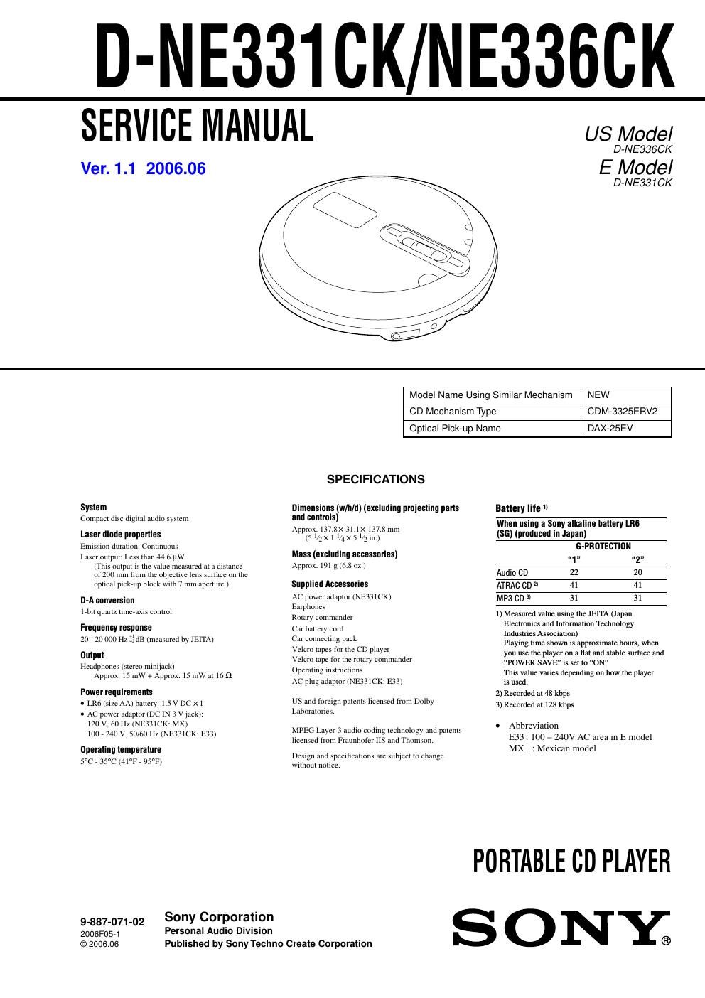
Sony d ne 336 ck service manual

This is the 38 pages manual for sony d ne 336 ck service manual.
Read or download the pdf for free. If you want to contribute, please mail your pdfs to info@audioservicemanuals.com.

Page: 1 / 38
left right
sony d ne 336 ck service manual

Extracted text from sony d ne 336 ck service manual (Ocr-read)


Page 1

D-NE331CK/NE3360K

SERVICE MANUAL

Ver. 1.1 2006.06

US Model

D-NE336CK

E Model

D-NE331 CK

Model Name Using Similar Mechanism NEW

CD Mechanism Type

CDM-3325EFIV2

Optical Pick-up Name

DAX-25EV

SPECIFICATIONS

System Dimensions (w/h/dl (excluding pruienting parts
Compact disc digital audio system and controls)
. . Approx. 137.8x 31,1>< 137,3 mm
Laser diode properties (5 1/2X 1 1,,3X 5 1/2 1.)
Emission duration, Continuum
Laset output. Less than 44 (7 11W
(This output is the tntue measured at a distance
ot2t10 mm horn the trbjecllve tens su toe on the

Mass (excluding accessories)
Approx. 191 g (ox 0L.)

option] pickrtlp block With 7 mm Apelture.) Supplied Accessories
D-A conversion ac pout er adaptor (NE331CK)
earphones

17bit sluJIlL limerdxia control
Rotary eotrttnantter

Frequency response Car battery cord
20 , 20 000 H; ldts (measured by 1h1TA) Cm connecting puck

Velcro ta es l'orthe CD to er
Output P p y

Velcro tape {or the rotary commander
Operating instructions
AC plug adaptor (Nh331CK, 1533)

Headphones lsteteo ntiniyaek)
Approx 15 mW + Approx. 15 mW at to 9.

Power requirements

. LRf) (sue AA) battery. 1.5 v DC ><1

. AC power adaptor (DC [N 3 v Jack).
121) v. on Hz (NBMCK, MX)
101» 24t1v.50/ot1 Hz (BEESICK. p.13)

US and totergu patents licensed trout Dolby
Laboratories

MPEG Layer} audio coding technology and patents
licensed from Fruunltoter 115 and Thomson,
Operating temperature

. Design and specificattons are subject to Change
5°C , 35°C (41°F , 95W}

wnhnut notice,

Sony Corporation

9-887-071-02
2006F0571 Personal Audio Division
©2006.06 Published by Sony Techno Create Corporation

Battery lite "

W
(56) (produced in Japan)

G'PRDTEBTION

of, 112"
Audio CD 22 20
ATRAC CD 2 41 41
MP3 CD 3 31 31

1) Measured value usmg the J'El'lA (Japan
Electromcs and Information Technology
Industries Association)
Playing time shown is approxnnate hours, when
you use the player on a flat and stable surface and
POWER SAVE" is set to ON
Ttus value vanes depending on how the player
ts used.

2) Recorded at 48 kbps

3) Recorded at 128 kbps

- Abbreviation
E33: 100 - 240V AC area in E model
MX : Mexican model

PORTABLE co PLAYER
S 0 NYC.)

Page 2

D-NE331CK/NE336CK

llntes nn the AC: power adaptor

- Disconnect all power sources when the player is
not to be used for a long time.

- Use only the AC power adaptor supphed. If your
player is not supplied with an AC power adaptor.
use an AC7E30HG AC power adaptor". Do not
use any other AC power adaptor. It may cause a
malfunction.

* Not available in Australia and some other
regions. Ask your dealer for detailed
information.

Polarity of the plug
M 2

Do not touch the AC power adaptor with wet
hands.

Connect the AC power adaptor to an easily
accessible AC outlet. Should you notice an
abnormality in the AC power adaptor. disconnect it
from the AC outlet immediately.

Note on the car battery cord

The 3 V DC plug supplied with car battery
cord conforms to the proposed standards
of the Japan Electronics and Information
Technology Industries Association (JEITA).
Do not connect it to other players.

Polarity ol the plug
o-e

(JElTA standards)
Notes on chip component replacement
0 Never reuse a disconnected chip component.
0 Notice that the minus side of a tantalum capacitor may be
damaged by heat.

Flexible Circuit Board Repairing
0 Keep the temperature of the soldering iron around 270 C
during repairing.
0 Do not touch the soldering iron on the same conductor of the
circuit board (within 3 times).
0 Be careful not to apply force on the conductor when soldering
or unsoldering.

CAUTION

Use of controls or adjustments or performance of procedures
other than those specified herein may result in hazardous radiation
exposure.

SAFETY-RELATED COMPONENT WARNING I!

COMPONENTS IDENTIFIED BY MARK A OR DOTTED LINE
WITH MARK A ON THE SCHEMATIC DIAGRAMS AND IN
THE PARTS LIST ARE CRITICAL T0 SAFE OPERATION.
REPLACE THESE COMPONENTS WITH SONY PARTS WHOSE
PART NUMBERS APPEAR AS SHOWN IN THIS MANUAL OR
IN SUPPLEMENTS PUBLISHED BY SONY.

2

3.

3.1_
3-2.
373.

3.4_

4.

471.
472.
43.
474.

4751

476.
477.

5.

571.
52.
573.

6.

TABLE OF CONTENTS


SERVICING NOTES 3
GENERAL 4
DISASSEMBLY

Disassembly Flow ..... 5
Cabinet Lower Sub , Upper Lid Sub As 5
MAIN Board, Optical Pick-Up A ' 'y

(CDM-3325ERV2) .................. 6
SWITCH Board ............................................................... 6
DIAGRAMS

Schematic Diagram 7 MAIN Board (1/3) 7 .................... 9
Schematic Diagram 7 MAIN Board (2/3) 7 10
Schematic Diagram 7 MAIN Board (3/3) 7 11
Printed Wiring Board

7 MAIN Board (Component Side) 7 ............................... 12
Printed Wiring Board

7 MAIN Board (Conductor Side) 7 ...... 13
Printed Wiring Board 7 SWITCH Board 14
Schematic Diagram 7 SWITCH Board 7 ........................ 15
EXPLODED VIEWS

Upper Lid Section ..... 21
Cabinet Lower Section . 22
Optical Pick-Up Section (CDM-3325ERV2) . 23
ELECTRICAL PARTS LIST ................................ 24