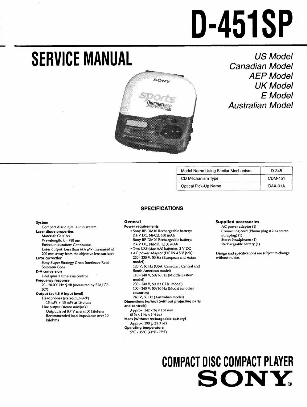
Sony d 451 sp service manual

This is the 26 pages manual for sony d 451 sp service manual.
Read or download the pdf for free. If you want to contribute, please mail your pdfs to info@audioservicemanuals.com.

Page: 1 / 26
left right
sony d 451 sp service manual

Extracted text from sony d 451 sp service manual (Ocr-read)


Page 1

L

n-A_51

SP

TEAMCE MANUAL

US Model
Canadian Model
AEP Model

UK Model

E Model
Australian Model

System
Compact disc digital audio system
Laser diode properties
Material: CaAlAs
Wavelength: l = 780 nm
Emission duration: Continuous
Laser output: Less than 44.6 uW (measured at
200 m away from the objective lens surface!
Error correction
Sony Super Strategy Cross lnterleave Reed
Solomon Code
D-A :onversion
1-bit quartz time-axis control
Frequency response
20 - 20,000 Hz tldli (measured by BIA] CP-

307)
Output (at 45 V input level)

Headphones (stereo miniiadd
15 mW + 15 mW at 16 ohms

Line output (stereo minijack)
Output level 07 V rrns at 50 kilohms
Recommended load impedance over 10
kilohms

Model Name Using Similar Mechanism D-345

CD Mechanism Type CDM»451

Optical Pick»Up Name BAX-01 A
SPECIFICATIONS

General
Power requirements
- Sony BP-DMIO Rechargeable battery:

2.4 V DC, Ni-Cd, 650 mAh

Sony BP-DMZO Rechargeable battery:

2.4 V DC, NiMH 1,100 Mk

0 Two LR6 (size AA) batteries: 3 V DC
0 AC power adaptor (DC IN 4.5 V jack):

220 - 230 V, 50 HzlEuropean and Asian

model)

120 V, 60 Hz (USA, Canadian, Central and

South American model)

110 - 240 V, 50/ 60 Hz (Middle Eastern

model)

230 - 240 V, 50 Hz (U.K. model)

100 - 240 V, 50/60 Hz (Model for other

countries)

240 V, 50 Hz (Australian model)
Dimensions (wlh/d) (without projecdng parts
and controls)

Approx,142 X 36 x158 mm
(5%)(1 Vioxé Viin.)
Mass (without rechargeable battery)
Approx 390 3 (123 oz)
Operating temperature
5°C - 35°C (41°F - 95°F)

Supplied accessories
AC power adaptor (1)
Connecting cord (Phone plug x 2 H stereo
miniplug) (1)
Stereo headphones (l)
Rechargeable battery (I)

Design and specificatiom are subject to change
without notice

COMPACT DISC COMPACT PLAYER
S ON Y®

Page 2

6» l.
6-2.
6-3.

TABLE OF CONTENTS

SERVICE NOTE .................................................... 6
DISASSEMBLY ....................................................... 7
SERVICE MODE ..................................................... 8
ELECTRICAL ADJUSTMENTS 9
DIAGRAMS

Printed Wiring Boards
Schematic Diagram

lC Pin Function Description 28
EXPLODED VIEWS ................................................. 30
ELECTRICAL PARTS LIST ............................. 33

Flexible Circuit Board Repairing

0 Keep the temperature of the soldering iron around 270 C

during repairing.

0 Do not touch the soldering iron on the same conductor of

the circuit board (within 3 times),

0 Be careful not to apply force on the conductor when solder-

ing or unsoldering.

Notes on chip component replacement

0 Never reuse a disconnected chip component.

0 Notice that the minus side of a tantalum capacitor may be

damaged by heat.

SAFETY-RELATED COMPONENT WARNINGI!

COMPONENTS IDENTIFIED BY MARK A OR DO'I'I'ED
LINE WITH MARK A ON THE SCHEMATIC DIAGRAMS
AND IN THE PARTS LIST ARE CRITICAL TO SAFE
OPERATION. REPLACE THESE COMPONENTS WITH
SONV PARTS WHOSE PART NUMBERS APPEAR AS
SHOWN IN THIS MANUAL OR IN SUPPLEMENTS PUB-
LISHED BY SONY.

ATTENTION AUCOMPOISANT AYANT RAPPORT
A LA SECURITE!

LEs COMPOSANTS IDENTIFIES PAR UNE MARQUE A
sun LEs DIAGRAMMES SCHE'MATIOUES ET LA LISTE
DES PIECES sour camouEs POUR LA sécunrrE
DE FONCTIONNEMENT. NE REMPLACER CES com-
POSANTS QUE PAR DEs PIECES souv DONT LEs
NUMEnos sour DONNés DANS CE MANUEL ou
DANS LEs SUPPLEMENTS PUBLiEs PAH souv.

This Compact Disc player is classified as a CLASS 1
LASER product.

The CLASS 1 LASER PRODUCT label is located on
the bottom exterior.

CLASS I LASER PRODUCT
LUOKAN I LASERLAITE

KLASS I LASERAPPARAT

CAUTION

Use of controls or adjustments or performance of pro-
cedures other than those specified herein may result in
hazardous radiation exposure.