Sony d 375 service manual

This is the 14 pages manual for sony d 375 service manual.
Read or download the pdf for free. If you want to contribute, please mail your pdfs to info@audioservicemanuals.com.

Page: 1 / 14
left right
sony d 375 service manual

Extracted text from sony d 375 service manual (Ocr-read)


Page 1

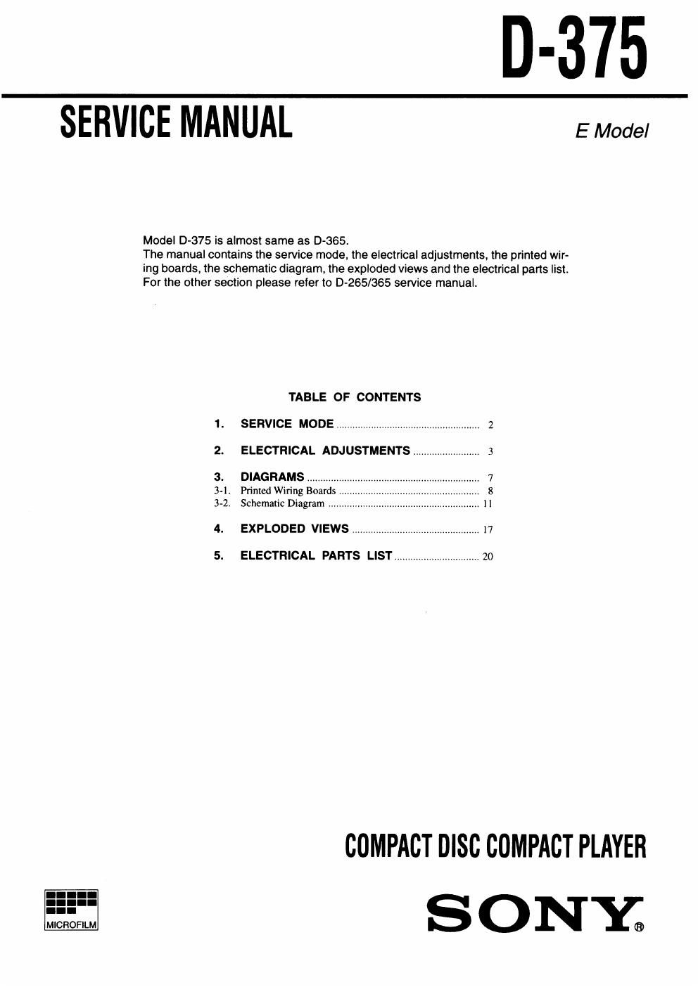
D-375

SERVICE MANUAL EModel

Model D-375 is almost same as D4365.

The manual contains the service mode, the electrical adjustments, the printed wir-
ing boards, the schematic diagram, the exploded views and the electrical parts list.
For the other section please refer to D-265/385 service manual.

TABLE OF CONTENTS
1. SERVICE MODE ..................................................... 2
2. ELECTRICAL ADJUSTMENTS......................,.. 3
3. DIAGRAMS .............

3-]. Printed Wiring Boards .
3-2, Schematic Diagram

4. EXPLODED VIEWS ................................................ 17
5. ELECTRICAL PARTS LIST ................................ 20

COMPACT DISC COMPACT PLAYER
S 0 NY;

Page 2

SECTION 1
SERVICE MODE

Service Mode (Service program) 6.

The equipment is provided with a service program built in the mi-

crocomputer, like conventional models 7.

Service program operation methods are described in the following.

we (FF!)
The optical pick-up
s moved inwardly
DH (FF)
[The optical pick-up
is moved outwardly

[All servos are turned OFH

HI (PLAY/PAUSE)
Focus is turned UN to
effect draw-in mode

HOLD OFF -. 0N REPEAT/ENTER

[Be sure to turn OFF 7795"9 995 mode]
the HOLD switch PLAY MODE while Messing

(If ON, pressing each I-Tracking servo and sled :|

key is deactivated) ervo are turned ON

Descriptions in [ ] indicate major operations in the service
mode. For more inlormatrion, see Step 2.
Fig. 1 Layout of each key

0 Step 1 (Service mode setting methods)

1, Tum OFF the HOLD switch with external power supply dis-
connected (power is not applied to the set)

2. Solder across the TEST terminals (TAP802) (pin @, IC80]
(TEST) is grounded)

3. Connect an external power supply.

Thus. the set is switched to the service mode.

0 Step 2 (Operation in the service mode)

1. Once the service mode is effected, the LCD displays 5 indica-
tions each of which is repeatedly displayed
However, the following operations can be activated even if LCD
indication is effected.

2. By pressing the PM or I44 key, the optical pick-up is mov-
able inwardly or outwardly However, if this is activated. track-
ing servo and sled servo are turned OFF. so it can be turned ON
by pressing the PLAY MODE key if required.

3. By pressing the REPEAT/ENTER key, the tracking gain-up
mode becomes active.

4. By pressing the HI key, focus is turned ON from focus search-
ing while entering CLV-S (pull-in mode),

Without disc, focus searching is repeated continuously.

5. By pressing the PLAY MODE key, tracking servo, sled servo

and CLV~A (servo in PLAY) are turned ON

2.

When 4. an 5. are performed, playing begins. No muting is ON
in the service mode.

By pressing the I key, all servos (focus, tracking and sled) are
turned OFF However, the disc motor revolves for a while by
inema.

. Step 3 (Resetting of service mode)
I (STOP) 1.

Be sure to disconnect the external power supply and remove
the solder bridge at the TEST terminals connected before in
setting.

The set thus becomes available for normal operation.

- MAIN BOARD - (Component Side)

swttcv umr


TAPBOZ
(TEST)

r W427
Ichut

Fly. 2 Location 0! Test terminal