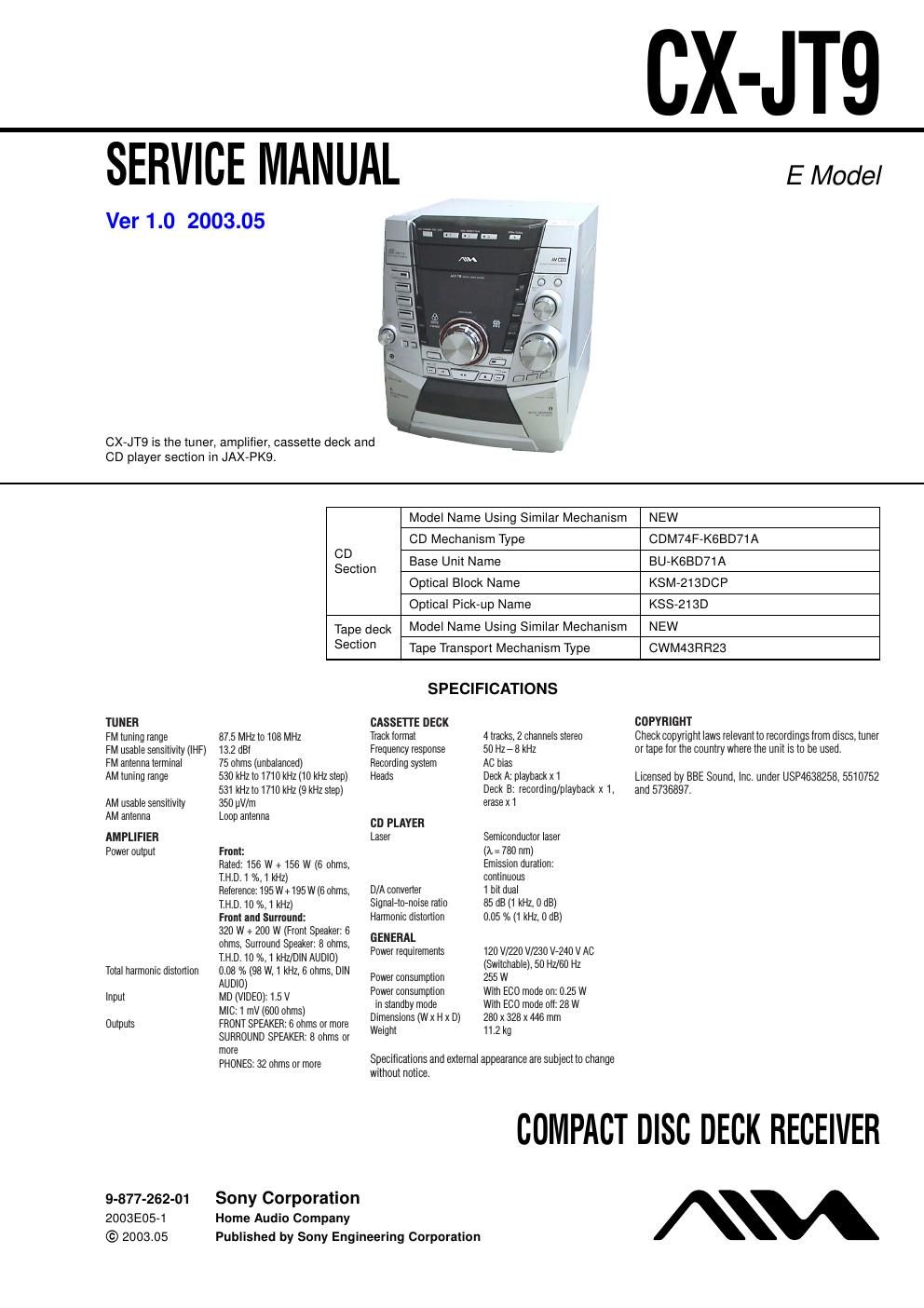
Sony cx jt 9 service manual

This is the 88 pages manual for sony cx jt 9 service manual.
Read or download the pdf for free. If you want to contribute, please mail your pdfs to info@audioservicemanuals.com.

Page: 1 / 88
left right
sony cx jt 9 service manual

Extracted text from sony cx jt 9 service manual (Ocr-read)


Page 1

CX-JT9

SERVICE MANUAL

Ver 1.0 2003.05

CX-JT9 is the tuner, amplifier, cassette deck and
CD player section in JAX-PKQ.

E Model

TUNER

FM tuning range

FM usable sensitwity (lHF)
FM antenna Ierminal

AM tuning range

AM usable sensitiiiity
AM antenna

AMPLIFIER
Power outpul

Total harmonic distortion

87.5 MHZ to 108 MHZ

13.2 (131

75 ohms (unbalanced)

530 kHz to 1710 kHz (10 kHz step)
531 kHz to 1710 kHz (9 kHz step)
350 uV/m

Loop antenna

Front:

Raled: 156 W + 156 W (6 ohms,
TH D 1 n/n,1 kHz)

Reference: 195 W+195 W (6 ohms,
TH 010%,1kHZ)

Front and Surround:

320 W + 200 W (Fronl Speaker 6
ohms, Surround Speaker 8 ohms,
TH D 10 %,1kHZ/DINAUD|0)
008 A: (98 W, 1 kHz, 6 ohms, DIN
AUDIO)

Track lormat 4 tracks, 2 channels stereo

Frequency response 50 Hz , 8 kHz

Recording syslem AC oias

Heads Deck A: playback x1
Deck B: recording/playback x 1,
erase x1

CD PLAVER

Laser Semiconduclor laser
(A : 780 nm)
Emission duralion:
continuous

D/A converler 1 bit dual

85 dB (1 kHz, 0 dB)
0.05 % (1 kHz, 0 dB)

Signalrlornoise ratio
Harmonic distortion

GENERAL

Power iequirements 120 V7220 V/230 V7240 V AC
(Swilchaole), 50 HZ/fil) Hz
Power consumption 255 W

Power consumption With E00 mode on: 0.25 W

Model Name Using Similar Mechanism NEW
CD Mechanism Type CDM74F-K6BD71 A

gEction Base Unit Name BU-K6BD71A
Optical Block Name KSM-213DCP
Optical Pick-up Name KSS-213D

Tape deck Model Name Using Similar Mechanism NEW

Section Tape Transport Mechanism Type CWM43RR23

SPECIFICATIONS
CASSETTE DECK COPYRIGHT

Check copyright laws relevanlto recordings Irom discs, timer
or tape lor the counlry where the unit is lo be used.

Licensed by BBE Sound, Inc. under USPAEBBZSB, 5510752
and 5736897.

COMPACT DISC DECK RECEIVER

mm" mgfiflggbfggms) in standby mode With ECO mode oil: 28 w
Outputs FRONT SPEAKER: 6 ohms or more DIWSHSIOHS (W X H x D) 280 x 328 X 446 mm
sunnouno SPEAKER 8 ohms or we'gm 1 2 9
mam 32 0th m more Specifications and external appearance are subject to change
Without notice
9-877-262-01 Sony Corporation
2003E05-1 Home Audio Company
© 2003.05 Published by Sony Engineering Corporation

Page 2

CX-JT9

Notes on chip component replacement

Never reuse a disconnected chip component.
Notice that the minus side ofa tantalum capacitor may be dame
aged by heat.

Flexible Circuit Board Repairing

Keep the temperature of the soldering iron around 270 C dur-
ing repairing.

Do not touch the soldering iron on the same conductor of the
circuit board (within 3 times).

Be careful not to apply force on the conductor when soldering
or unsoldering.

CAUTION

Use of controls or adjustments or performance of procedures
other than those specified herein may result in hazardous rae
diation exposure.

This appliance is classified
CLASSt LASER PRODUCT as a CLASS I LASER
worm l LASER rmg product.

TI'IlS label ls located on the
rear exterior.

KLASS r LASER APPARAI

SAFETY-RELATED COMPONENT WARNINGII

COMPONENTS IDENTIFIED BY MARK A OR DOTTED
LINE WITH MARK A ON THE SCHEMATIC DIAGRAMS
AND IN THE PARTS LIST ARE CRITICAL T0 SAFE
OPERATION. REPLACE THESE COMPONENTS WITH
SONY PARTS WHOSE PART NUMBERS APPEAR AS
SHOWN IN THIS MANUAL OR IN SUPPLEMENTS PUB-
LISHED BY SONY.