Sony cpm d 3 service manual

This is the 6 pages manual for sony cpm d 3 service manual.
Read or download the pdf for free. If you want to contribute, please mail your pdfs to info@audioservicemanuals.com.

Page: 1 / 6
left right
sony cpm d 3 service manual

Extracted text from sony cpm d 3 service manual (Ocr-read)


Page 1

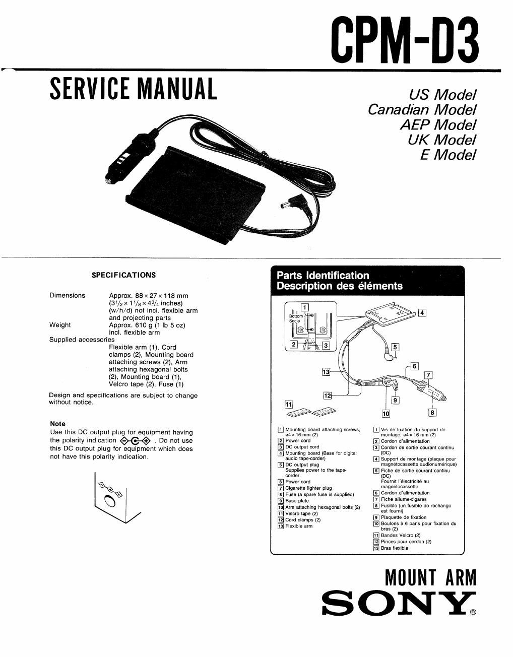
CPM-D3

SERVICE MANUAL us Model

Canadian Model
AEP Model

UK Model

E Model

SPECIFICATIONS Parts Identification

DescrIptIon des elements

Dimensions Approx. 88 x 27 x118 mm
(3 V2 x 1 Va x 43/4 inches)
(w/h/d) not incl, flexible arm
and projecting parts

Weight Approx. 610 g (1 lb 5 oz)
inclt flexible arm

Supplied accessories
Flexible arm (1), Cord
clamps (2), Mounting board
attaching screws (2), Arm
attaching hexagonal bolts
(2), Mounting board (1),
Velcro tape (2), Fuse (1)

Design and specifications are subjecl to change
without notice,

Note EM t' be d tt t-I EVsdelxannd sppovtde
- . . oun m er 3 ac mg screws. . . I u u
Use thIs DC output plug for equlpment havmg X163 (2) montage, 64x16 mm (2)
the polarity indication W . Do not use IE] Power cord 12 Cordon d'allmentation >
this DC output plug for equipment which does E C W? °° _ , El CW0" d9 some OWEN WWW
. . . . Y El Mounting board (Base for digital (DC)
not have lhls polarity IndIcatIon. and, lapemmfl) El Suppm de mamage (plaque pom,
El DC output plug magnetocassette audlonuménque)
Supplies power to the lepe- El Fiche do some oouvant cominu
comer. (DC)
El Power cord Foumit Iélectvicité au
§xQ l3 Olgarette lighter plug magnémcassellev
\Q El Fuse (a spare loss is supplies) El 00'60 d'fi'imemamn
Q E Base p. Flche allumecigares
{El Arm attaching hexagonal bolts (2) 5:32:35" 'USbe de {achinge
WC Fe (2) Plaquetts de iixalion
E cm clamps (2) Boulons a 6 pans pour tlxallon du
[E Flexible arm bras (2)

El Bandes Velcro (2)
[El Pinces pour cordon (2)
@ BIas flexible

MBUNT ARM

SONYa

Page 2

CPM-D3

SECTION 1
GENERAL

1-1. INSTALLATION

Install the mounting board
1 onto the arm.

Installation de la plaque de
montage sur le bras


\ I
A sistant seat
Siege passager

\

Flexible arm
Bras flexible

Screws


: /
Sliding rails J 2

Glissiéres

Note
Fix the unit so that ii does not disturb your diiving.

Bottom of the board
Fond de la plaquette


Remarque
Meltre on place l'appareil de tails tam qull ne gene pas Ia conduits,

2 install the arm.

Installation du bras

1 Loosen the mounting bolt of the 2 install the base plate and tighten the 3 install the arm.
sliding rail under the assistant seat. bolt. Fixer Ie bras.
Desserrer Ie boulon de montage de Placer la plaquette de fixation et
la glissiére du siege passager. serrer ls boulon.

Bolts
Boutons

Bolt
Boulon ®
. Selectable hole in
® accordance with the insert the bolt while
Base plate installation angle holding the arm.
Piaquette de lixation Orifice, au choix, lnsére, le boulon tout
59'0 langle en tenant le bras.

d'installation

To change the mounting board position, move it with the arm, not
with the board itself.
Make the mounting board as level as possible to reduce vibration.


Attach the digital audio tape-corder.
3 Fixation du magnétocassette
audionumérique

Booger ie bras flexible et non la plaquette de montage pour changer
la position de celIe-ci.
Pour réduire les vibrations, disposer la plaquette de niveau.

Do in this way. Not this way.
De cette maniere. Pas de cette mannere.

To remove
Dépose