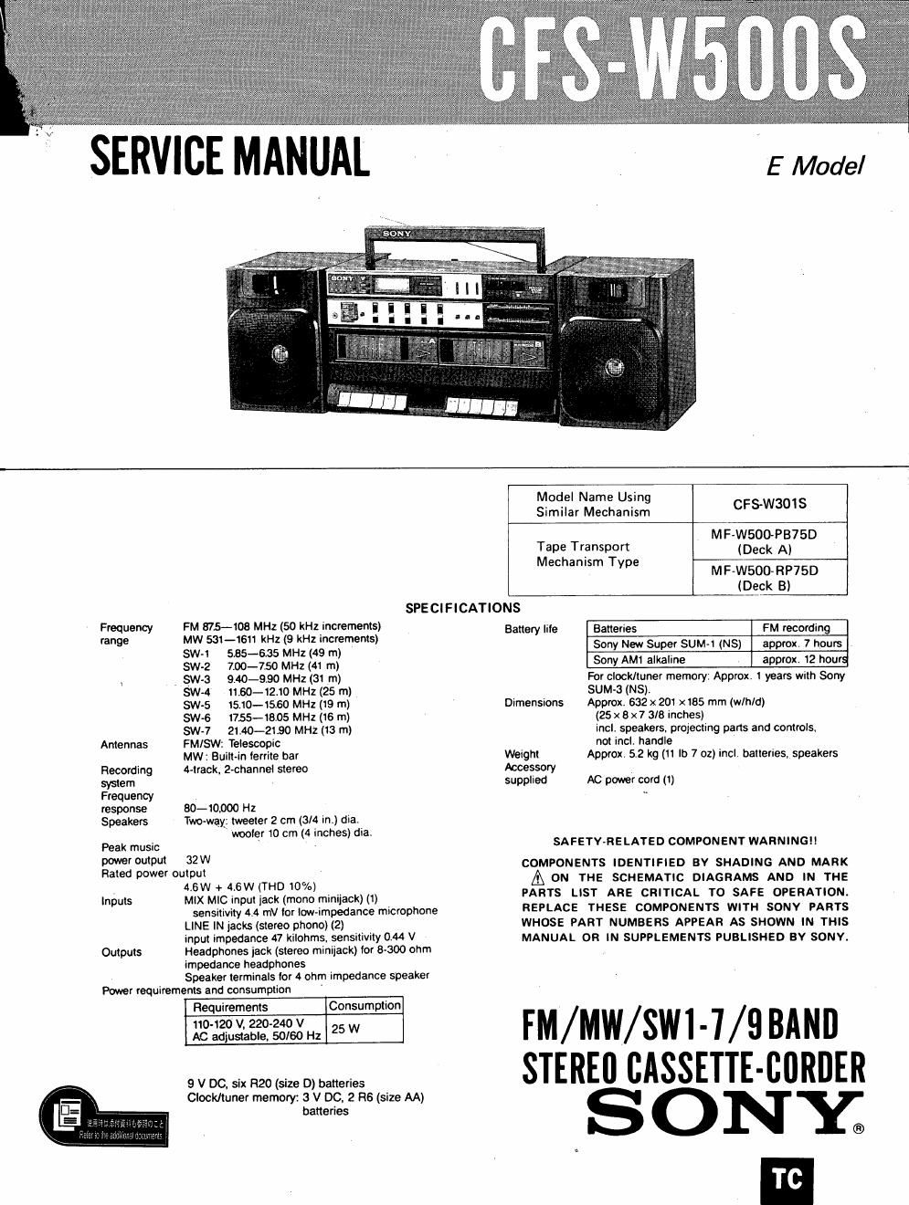
Sony cfs w 500 s service manual

This is the 29 pages manual for sony cfs w 500 s service manual.
Read or download the pdf for free. If you want to contribute, please mail your pdfs to info@audioservicemanuals.com.

Page: 1 / 29
left right
sony cfs w 500 s service manual

Extracted text from sony cfs w 500 s service manual (Ocr-read)


Page 1

SERVICE MANUAL

E Model

SPECIFICATIONS
Battery Iile Batteries FM recording

Frequency FM 875-108 MHz (50 kHz increments)
range MW 531-1611 kHz (9 kHz increments)
SW-1 535-635 MHz (49 m)
sw-2 7.00-7.50 MHz (4: m)
l _ SW-3 9.40-990 MHZ (31 m)
5W-4 11.60-12.10 MHz (25 m)
$W-5 15.10-15.60 MHz (19 m)
SW-G USS-18.05 MHz (16 m)
SW-7 2140-21490 MHz (13 m)

Antennas FM/SW: Telescopic
MW: Built Recording 4-track 2-channel stereo
system
Frequency
response 80-10000 Hz
Speakers Two~wa_y\: tweeter 2 cm (3/4 in) die.

woofer 10 cm (4 inches) dia.
Peak music
power output 32W
Rated power output
(6W + 4.6W (THU 10%)
Inputs MIX MIC input jack (mono minijack) (1)
sensitivity 4.4 mV lor low-impedance microphone
LINE IN jacks (stereo phone) (2)
input impedance 47 kilohms, sensitivity 0.44 V
Outputs Headphones jack (stereo minijack) lor 0300 ohm
impedance headphones
Speaker terminals lor 4 ohm impedance speaker
Power requirements and consumption '

Requirements Consumption

110-120 V. 220240 V 25 W
AC adjustable, 50/60 Hz

9 V DC, six H20 (size D) batteries
Clock/tuner memory: 3 V DC. 2 R6 (size AA)
batteries

Model Name Using

Similar Mechanism CFS-W3OIS
MF-W500PB7SD
Tape Transport (Deck A)

M r
ham Type MF-W500-RP75D

(Deck B)

Sony New Super SUM-I (NS) approx, 7 hours
Sony AMt alkaline approx. 12 NM

For clock/tuner memory: Approx, 1 years with Sony
SUM-3 (NS).

Dimensions Approx. 632 x 201 x165 mm (MM!)

(25 x 8 x7 3/3 inches)
incl. speakers, projecting pans and controls.
not incl. handle

Weight Approx. 5.2 kg (11 lb 7 oz) incl, batteries, speakers
Accessory

supplied AC power cord (1)

SAFETYARELATED COMPONENT WARNING

COMPONENTS IDENTIFIED BV SHADING AND MARK

A ON THE SCHEMATIC DIAGRAMS AND IN THE
PARTS LIST ARE CRITICAL T0 SAFE OPERATION.
REPLACE THESE COMPONENTS WITH SONY PARTS
WHOSE PART NUMBERS APPEAR AS SHOWN IN THIS
MANUAL OR IN SUPPLEMENTS PUBLISHED BY SONV.

FM/MW/SWI-7/9 BAND
STEREII CASSETTE-CBRDER

SONx

TC

Page 2

CFS-WSOOS

TABLE OF CONTENTS

Title Descrigtion Page Title Descrigtion Page
Specifications ..................... 1 2-3. Radio Section Electrical Adjustments ..... 9
Section 1. Outline Section 3. Diagrams
l~l. Location and Function of Controls ....... 2 34- Semiconductors Lead Layout --------- 12
1-2. To Set the Clock ................... 4 3-2. Mounting Diagram ................. B
1-3. To Use the Internal Timer ............. 4 3-3- 591191113th Diagram - Tuner Section - . . . 17
Section 2. Adjustments 3: 133:???) Piagram - Audio SeCtion - . . . i?
21. Mechanical Adjustments and Measurements . 6 - ' oc iagrams """""""""
2.2. Tape Recorder Section Electrical Section 4. Exploded Views and Parts List ......... 23
Adjustments ~~~~~~~~~~~~~~~~~~~~~~ 7 Section 5. Electrical Parts List ................ 28
SECTION 1
O UTL I N E

1-1. LOCATION AND FUNCTION OF CONTROLS
[IITWeeter

El Telescopic antenna
E] Handle

I3 Woofer

El Cassette holder A

E] Tape operation buttons

l A STOP/EJECT button
0 RECORD button (deck B only)-Pressing this will auto
malically depress > PLAY.

> PLAY button.

« REW (rewind, AMS) button (deck A)
REWIREVIEW (rewind/review) button (deck 8)

» FF (last~lon~ard. AMS) button (deck A)

FF/CUE (last-lorwardlcue) button
(Note: « and » do NOT release automatically at tape
end. Press IA STOP/EJECT)

ll PAUSE button

cassette holder 8

Clock/Timer operation buttons
CLOCK-to set clock
TlMER-to display or set timer-on time
SLEEP-tor timed radio play
STANDBY-to activate or turn oil wake-to-radio, wake-to-alarm

E] Clock/tuner display

OPR/BATT (operation/battery) indicator
Shows unit is in use. When glow becomes taint, change all
batteries.

IE FM STEREO indicator
Lights to show stereo reception. Use to find best tuning.

[E TIME SET/SCAN + I - buttons
@ BAND selector (FM/MW/SW)
@FM/MWISW PRESET TUNING buttons

[E MEMORY button

PHONES (headphones) lack (stereo mlnliack)

@ FUNCTION selector
Selects RADIO/LINE IN. TAPE or DUBBING. You can also choose
NORMAL or HIGH-SPEED clubbing,

RADIO/LINE IN switch

S-BAND GRAPHIC EOUALIZER controls
Use to tailor tone response to listening room or listening material.

fl) REC MUTE (Record muting) button
Use to add a silent section during recording.

E] 'I'APE SELECT (PB) switch (CrOz-METALINORM)
Use during playback to choose between Type I (normal) and Type
ll/Type lV(Cr01Imetal) tape types

TIMER/SLEEP switch

[E] BALANCE control
Use to improve stereo imaging, especially when speakers are not
symmetrically placed.

E} VOLUME control

g] SENS (sensitivity) (BX/LOCAL) selector ..

MIX Mlc (mixing mic) input jack (mono miniiack)
Speaker lock

Battery compartment

@ LINE lN jacks (left and right phono-iacks)
Allow connection ol other component (CD player eg.)

IE Speaker terminals

[2] AC IN socket
@ VOLTAGE SELECTOR