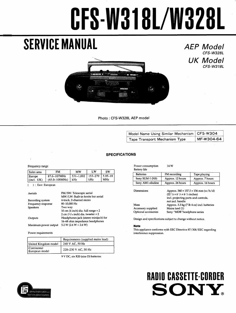
Sony cfs w 318 l service manual

This is the 29 pages manual for sony cfs w 318 l service manual.
Read or download the pdf for free. If you want to contribute, please mail your pdfs to info@audioservicemanuals.com.

Page: 1 / 29
left right
sony cfs w 318 l service manual

Extracted text from sony cfs w 318 l service manual (Ocr-read)


Page 2

TABLE OF CONTENTS

m Title Page
1_ GENERAL ............................................................... 3

2. DISASSEMBLY
2-li Cassette Holder
2-2i Front Cabinet
2.3 Dial POIHICI ................................... o ............. unuuus
2-4, MD Block
2-Si Tuner Board
2»6. Audio Board ............................................................ 6
2.7 Mme, ......................
2-8i Head Base and Head

3. MECHANICAL ADJUSTMENTS ........................ 3 AEP.G.EE model:AC:220-230V~50Hz 14w '6 :German

UK I: 0: ~ . :
4. ELECTRICAL ADJUSTMENTS ~~~~~~~~~~~~~~~~~~~~~~~~ s "was A 24"" 5° W 55 Easlfiuropean
5. DIAGRAMS

5-]. Block Diagram

5-2. Circuit Board Location "
5-3, Semiconductor Lead Layouts
54. Primed Wiring Boards-Audio Section-
S-S. Schematic Diagram-Audio Section-

MODEL IDENTIFICATION
-Specification Label-

UK model: CFS-W318L
AEP. G, EE model: CFS-W328L

S ONY; MODEL NO.

RADIO CASSETTE-CORDER

7////////////////////////////A

Center frequency:
This set employs three ceramic filters (CFI, 3. 4) which should
have the same color marking to identify their center frequency.

5-6, Schematic Diagram-Tuner Section-

5-7i Printed Wiring Board-Tuner Section- """"""""" 23
6. EXPLODED VIEWS
5.], Rear Cabinet Section ............ , ............................ 24

6-2, Front Cabinet Section
6-3. Deck A Tape Mechanism Section (1)
6-4. Deck A Tape Mechanism Section (2) "
6-5. Deck B Tape Mechanism Section (I) "


6-6, Deck B Tape Mechanism Section (2)

no r kl mo r k2 mark] markZ Center Frequency

red - 10.70MI-Iz

blue - 10,67MH2

orange - 10.73MHz

black - 10.64MH2

white - 10.16MHz

white white lOJSMHz

yellow - 10.79MHz

7. ELECTRICAL PARTS LIST ------------------------------ 31

SAFETY-RELATED COMPONENT WARNINGI I

COMPONENTS IDENTIFIED 8V MARK A OR DOTTED
LINE WITH MARK A ON THE SCHEMATIC DIAGRAMS
AND IN THE PARTS LIST ARE CRITICAL TO SAFE
OPERATION. REPLACE THESE COMPONENTS WITH
SONY PARTS WHOSE PART NUMBERS APPEAR AS
SHOWN IN THIS MANUAL OR IN SUPPLEMENTS PUB-
LISHED BV SONY.