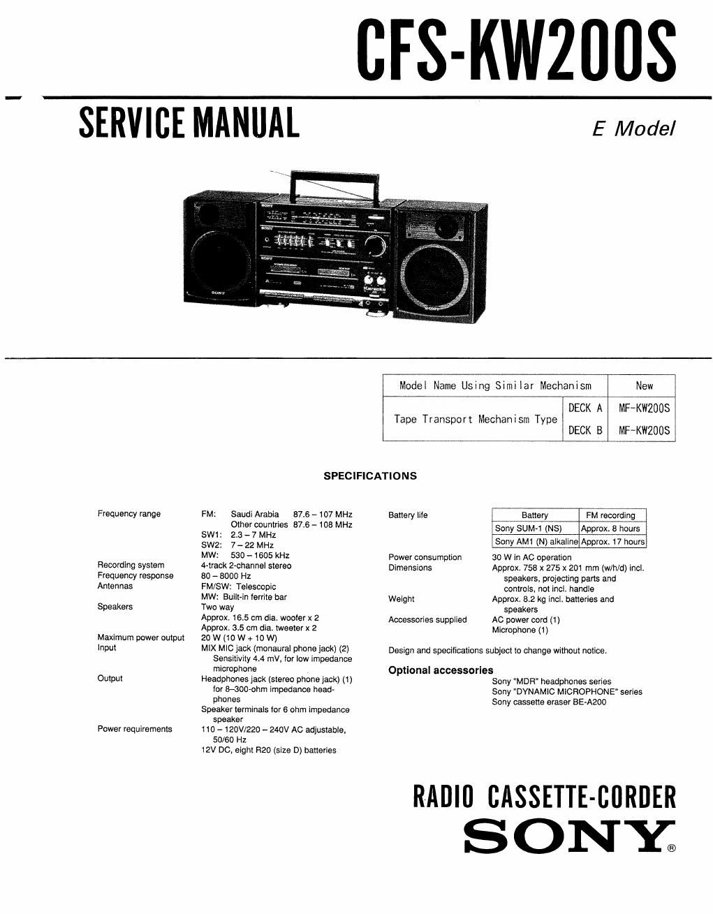
Sony cfs kw 200 s service manual

This is the 21 pages manual for sony cfs kw 200 s service manual.
Read or download the pdf for free. If you want to contribute, please mail your pdfs to info@audioservicemanuals.com.

Page: 1 / 21
left right
sony cfs kw 200 s service manual

Extracted text from sony cfs kw 200 s service manual (Ocr-read)


Page 1

CFS-KWZIIIIS

SERVICE MANUAL

E Model

Frequency range

Recording system
Frequency response
Antennas

Speakers

Maximum power output
Input

Output

Power requirements

Model Name Using Si mi la r Mechanism New
, DECK A MF~KW2008
Tape T ranspor t Mechan 1 sm Type
DECK B MFKWZUUS
SPECIFICATIONS
FM: Saudi Arabia 87.6 - 107 MHz Battery lite Battery FM recording
Other countries 87.6 - 108 MHz Sony SUM-1 (NS) Approx. 3 hours
SW 237 s AM1 N Ikl' A 17h r
SW2: 7_22 MHz ony ( )a alne pprox, DU 5
MW: 530 - 1605 kHz Power consumption 30 W in AC operation
4-week 2-channel stereo Dimensions Approx. 753 x 275 x 201 mm (w/h/d) incl,
80 - 8000 Hz speakers, projecting parts and
FM/SW: Telescopic controls, not incl. handle
MW: Built-in ferrite bar Weight Approx 82 kg incL batteries and
Two way speakers
Approx 165 cm dia, woofer X 2 Accessories supplied AC power cord (1)

Approx 35 cm dia. tweeter x 2

20W(10W+10W)

MIX MIC jack (monaural phone jack) (2)
Sensitivity 44 mV, for low impedance
microphone

Headphones jack (stereo phone Jack) (1)
tor 8-300-ohm impedance head-
phones

Speaker terminals Ior 6 ohm impedance
speaker

110 - 120V/220 - 240V AC adjustable,
50/60 HZ

12V DC, eight R20 (size D) batteries

Microphone (1)
Design and specifications subject to change without notice.
Optional accessories

Sony "MDR" headphones series

Sony DYNAMIC MICROPHONE" series
Sony cassette eraser BE-A200

RADIO CASSETTE-BORDER
SONXQ

Page 2

CFS-KWZOOS

TABLE OF CONTENTS
Sect i on Ti t l

m
Ta
9:
(D

Specifications ............................................ 1
1. GENERAL
Parts Identification ........................................ 3

2. DISASSEMBLY
Dial Pointer Installation

3. ADJUSTMENTS
3-1MECHANICAL ADJUSTMENTS
S-ZELBCTRICAL ADJUSTMENTS

4. DIAGRAMS

[C Block diagrams .......................................... 9
4-1.Printed Wiring Boards

Semiconductor Lead Layouts

4-2. Schematic diagram ...................................... 15
5. EXPLODED VIEWS ............................................ 20
6. ELECTRICAL PARTS LIST .................................... 25

-MODEL IDENTIFICATIONW
(Specification label)

SONY

MODEL N0 . CFSKW2UUS

RADIO CASSETTE-CORD
AC:110-l20/220~240V ~50/60Nz
DC:12V FLASHLIGHT BATTERY
R20 SIZE D X 8 0R EQUIVALENT

SAFETY-RELATED COMPONENT WARNING

COMPONENTS IDENT|FIED av MARK A on DOTTED
LINE WITH MARK A ON THE SCHEMAT|C DIAGRAMS Saudi Arabia model :MADE IN KOREA

AND IN THE PARTS LIST ARE CRITICAL To SAFE UNDER LICENSE FROM
OPERATION. REPLACE THESE COMPONENTS WITH SONY CORP.TOKYO JAPAN
SONI PARTS WHOSE PART NUMBERS APPEAR As

SHOWN IN TH|S MANUAL OR IN SUPPLEMENTS PUB-

LISHED By SONY. E model:SONY CORR