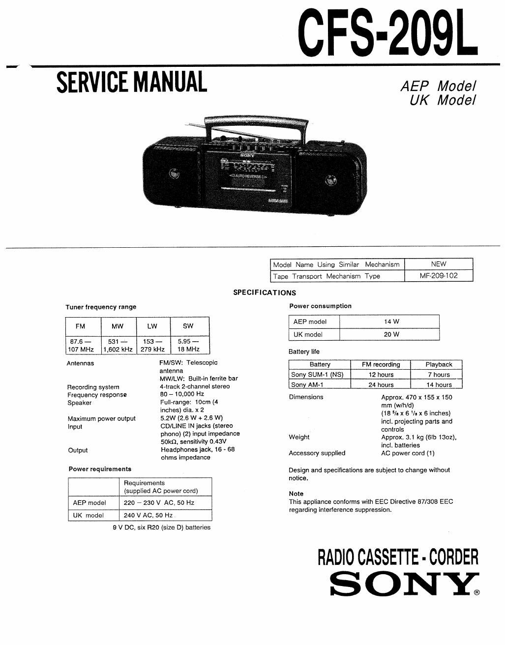
Sony cfs 209 l service manual

This is the 21 pages manual for sony cfs 209 l service manual.
Read or download the pdf for free. If you want to contribute, please mail your pdfs to info@audioservicemanuals.com.

Page: 1 / 21
left right
sony cfs 209 l service manual

Extracted text from sony cfs 209 l service manual (Ocr-read)


Page 1

CFS-209L

SERVICE MANUAL AEP Model

UK Model

y..- «Ammammn

Model Name Using Similar Mechanism NEW
Tape Transport Mechanism Type M92094 02
SPECIFICATIONS
Tuner frequency range Power consumption
FM MW LW SW AEP model 14 W
UK model 20 W
87,6 - 531 - 153 - 5.95 -
107 MHz 1,602 kHz 279 kHz 18 MHz Battery life
Antennas [Wt/SW: Telescopic Battery FM recording Playback
an enna
MW/LW: Built-in ferrite bar 5°"Y SW (3) 2 W" 7 00s
Recording system 4-track 2-channel stereo Sony AM~1 24 hours 14 hours
Frequency response 80 - 10.000 Hz . .
Speaker Full-range: 10cm (4 Dimensmns :fizxflgo x 155 x 150
imhes) dia' x 2 (18 5I x s v x 6 inches)
Maximum power output 5.2W (2.6 W + 2.6 W) incl lroect arts and
Input CD/LINE lN jacks (stereo contrilsl "9 p
none 2 in ut im eoance ,
gokQLIersilIiD/ity ogav wegh ,Appmx- 33 kg (5 1302),
H . ~ 68 . incl. batteries
Output $3235.13 g' 16 Accessory supplied AC power cord (1)

Power requirements Design and specifications are subject to change without

, notice.
Requirements
(supplied AC power cord) Note
AEP model 220 ~ 230 V AC. 50 Hz This appliance conforms with EEC Directive 87/308 EEC
regarding interference suppression.
UK model 240 V AC. 50 Hz

9 V DC. six R20 (size D) batteries

FlADlO CASSETTE - CORDER

SONE

Page 2

CFS-209L


TABLE OF CONTENTS
Section Title Page
Specifications ............................................................... 1
1. GENERAL
L/ocation and Function of Controls~~
Tape Playback
Listening to the Radio ................................................ 4

2. DIAL POINTER INSTALLATION
Dial pointer and Dir Indicator Installation --------------------- S

3. ADJUSTMENTS
3-1. Mechanical Adjustments ~ ~
3-2. Electrical Adjustments


4. DIAGRAMS
4-1. Printed Wiring Boards ~ 10
4-2. Schematic Diagram ------ ~ 13
5_ EXPLODED VIEWS .............................................. 17
s. ELECTRICAL PARTS LIST ~~~~~~~~~~~~~~~~~~~~~~~~~~~~~~~~~ 22
MODEL IDENTIFICATION SAFETY-RELATED COMPONENT WARNINGII
- Model Number Label - COMPONENTS IDENTIFIED BY MARK A on DOTTED

LINE WITH MARK A ON THE SCHEMATIC DIAGRAMS
AND IN THE PARTS LIST ARE CRITICAL TO SAFE
OPERATION. REPLACE THESE COMPONENTS WITH


S ON

MODEL NO.CFS-209L SONY PARTS WHOSE PART NUMBERS APPEAR As
---RADIO CASSETTE-CORDER SHOWN IN THIS MANUAL OR IN SUPPLEMENTS PUB-

////////////////////// SHED BY my.

AEP model : AC 220-230V~50Hz
UK model : AC 240V~50Hz