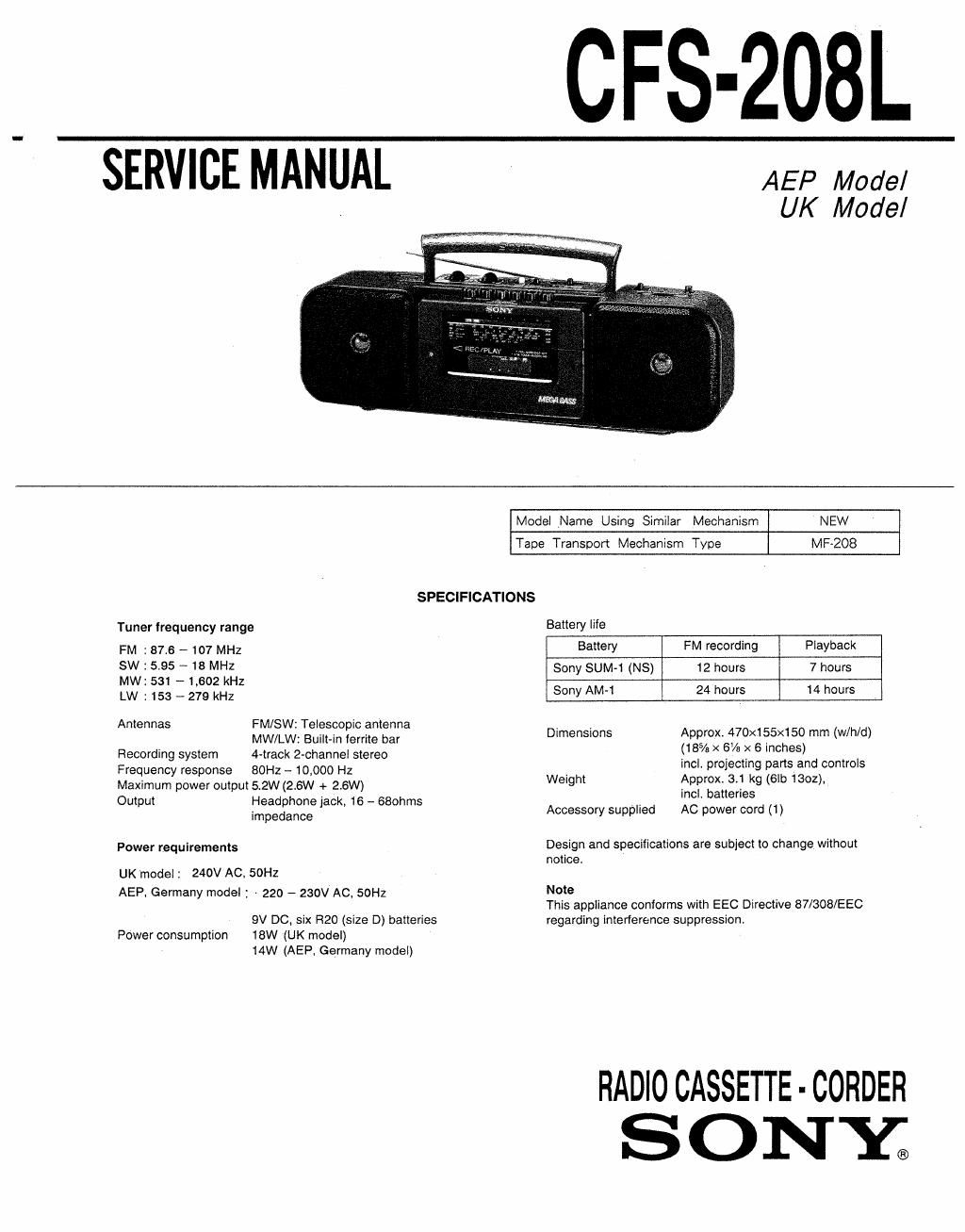
Sony cfs 208 l service manual

This is the 21 pages manual for sony cfs 208 l service manual.
Read or download the pdf for free. If you want to contribute, please mail your pdfs to info@audioservicemanuals.com.

Page: 1 / 21
left right
sony cfs 208 l service manual

Extracted text from sony cfs 208 l service manual (Ocr-read)


Page 1

CFS-208L

SERVICE MANUAL

AEP Model
UK Model

Model Name Using Similar Mechanism NEW
Tape Transport Mechanism Type MF-208
SPECIFICATIONS
Tuner frequency range Battery life
FM : 87.6 A 107 MHZ Battery FM recording Playback
5W 595 3 MHZ Sony SUM-1 (NS) 12 hours 7 hours
MW: 531 ~1,602 kHZ
Lw ; 153 _ 279 kHz Sony AM-1 24 hours 14 hours
Antennas FM/SW: Telesmpm antenna Dimensions Approx. 470x155><150 mm (w/h/d)

MW/LW: Built-in ferrite bar
Recording system 4-track 2-channel stereo
Frequency response BOHz - 10,000 Hz
Maximum power output 5.2W (2.6W + 2,6W)
Output Headphone jack, 16 - £580th
impedance

Power requirements
UKmodei: 240V AC, 50Hz
AEP. Germany model : - 220 - 230v Ac. 50Hz

9V DC, six R20 (size D) batteries
18W (UK model)
14W (AEP, Germany model)

Power consumption

Weight

Accessory supplied

(18% x 6% x 6 inches)

incl. projecting parts and controls
Approx,3r1 kg (61b 1302),

incL batteries

AC power cord (1)

Design and specifications are subject to change without

notice.

Note

This appliance conforms with EEC Directive 87/308/EEC
regarding interference suppression.

RADIOCASSETTE-CORDER
SONYE

Page 2

CFS-208L

TABLE OF CONTENTS

Section Title Page

Specifications

1. GENERAL
Location and Function of Controlsw
Tape Playback ~~~~~~~~~~
Listening to the Radio

2. DIAL POINTER INSTALLATION
Dial pointer Installation ---------------

3. ADJUSTMENTS
34, Mechanical Adjustments
3-2. Electrical Adjustments


4. DIAGRAMS
4-1. Pnnted Wiring Boards

4-2, Schematic Diagram 13
5. EXPLODED VIEWS ......... a .................................... 17
6. ELECTRICAL PARTS LIST ................................... 21

MODEL IDENTIFICATION
~ Model Number Label -


SONYe
MODEL NO. CFS-ZOBL

RADIO CASSETTE -CORDER

SAFETY-RELATED COMPONENT WARNING! I

COMPONENTS IDENTIFIED BY MARK A 0R DOTTED
LINE WITH MARK A ON THE SCHEMATIC DIAGRAMS
AND IN THE PARTS LIST ARE CRITICAL TO SAFE
OPERATION. REPLACE THESE COMPONENTS WITH
SONY PARTS WHOSE PART NUMBERS APPEAR AS
SHOWN IN THIS MANUAL OR IN SUPPLEMENTS PUB»
LISHED BY SONY.

UK model : AC 240V~50Hz
AEP, Germany model : AC 220-230V~50Hz