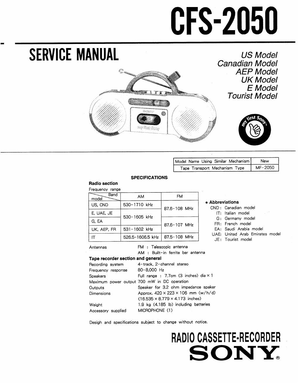
Sony cfs 2050 service manual

This is the 18 pages manual for sony cfs 2050 service manual.
Read or download the pdf for free. If you want to contribute, please mail your pdfs to info@audioservicemanuals.com.

Page: 1 / 18
left right
sony cfs 2050 service manual

Extracted text from sony cfs 2050 service manual (Ocr-read)


Page 1

CFS-2050

SERVICE MANUAL us Model

Canadian Model
AEP Model
UK Model

E Model
Tourist Model


Model Name Using Similar Mechanism New
Tape Transport Mechanism Type MF-2050

SPECIFICATIONS
Radio section
Frequency range
Band AM FM
model .
US. CND 530-1710 kHz 0 Abbrevnatlons
876-108 MHz CND: Canadian model
5 UAE- JE IT: Italian model
G, EA 530-1605 kHz G: Germany model
876-107 MHz FR: French model
UK, AEP. FR 531-1802 kHz EA: Saudi Arabia model
IT 526 5-18065 kHz 875-108 MHz UAE: United Arab Emirates model
' ' JE: Tourist model
Antennas FM : Telescopic antenna

AM : Built-in ferrite ber antenna
Tape recorder section and general

Recording system 4-track. Z-channel stereo

Frequency response 80-8.000 Hz

Speakers Full range : 7.7cm (3 inches) dia X 1

Maximum power output 700 mW in DC operation

Outputs Speaker for 3.2 ohm impedance spaker

Dimensions Approx. 420 X 223 X 106 mm (w/ h/ d)
(16.535 >< 8.779 X 4.I73 inches)

Weight 1.9 kg (4.185 lb) including batteries

Accessory supplied MICROPHONE (l )

RADIO CASSETTE-RECORDER

SONE

Page 2

CPS-2050

SECTION 1
GENERAL
TABLE OF CONTENTS LOCATION AND FUNCTION OF CONTROLS
m Ltle Reg:
1. GENERAL .......................................... 2

2. DISSASEMBLY

2-1. Removal of Cassette Holder ~~~~~~~~~~~~~~~~~~~ 5
2-2. Removal of Cabinet and Mechanism Deck. 5
2-3. Removal of Main Board ....................... 5
2-4. Removal of Speaker (SP101, SP201) --------- 5
2-5_ Dial Pointer Setting ........................... 6

3. ADJUSTMENTS
3- 1. Mechanical Adjustments and Measurements~~~ 7

3-2. Electrical Adjustment .......................... 7
4. DIAGRAMS

4-1. Semiconductor Lead Layouts ----------------- 10
4-2, Printed Wiring Boards ........................ 10
4-3, 1C Block Diagrams .......................... 13
4-4. Schematic Diagram ........................... 13
5. EXPLODED VIEWS

5.1. General ........................................ 15
5-2. Mechanism Deck (1) -- .. 17
5-3. Mechanism Deck (2) .......................... 18
6. ELECTRICAL PARTS LIST ~~~~~~~~~~~~~~~~~~~~~~~~~ 19

'5 Handle
:2 MIX MIC 1. MIX MIC 2 (microphonenacks
E Microphone
we Microphone holder
6 TUNING control
' .FIEC (record) button
4 PLAY button
» HEW (rewind)/REVIEW button
Speakers
Cassette holder
ti « FF (fast forward)/CUE button
12 I STOP/EJECT button
ti: CPR/BAIT power light/battery checker
try VOLUME control
16' TONE control
16 Function selector
17' Q HEADPHONES jack
123 BALANCE control
it; Antenna
:0 DO IN 6 V (external power input) jack
fit FM MODE/ISS selector

Ema rgc