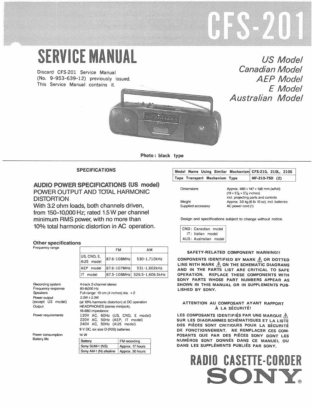
Sony cfs 201 service manual

This is the 20 pages manual for sony cfs 201 service manual.
Read or download the pdf for free. If you want to contribute, please mail your pdfs to info@audioservicemanuals.com.

Page: 1 / 20
left right
sony cfs 201 service manual

Extracted text from sony cfs 201 service manual (Ocr-read)


Page 1

SERVICE MANUAL

Discard CFSv201 Service Manual
(No. 9-953-639-12) previously issued.
This Service Manual contains it.

US Model
Canadian Model
AEP Model

E Model
Austral/an Model

Photo: black type

SPECIFICATIONS

AUDIO POWER SPECIFICATIONS (US model)

POWER OUTPUT AND TOTAL HARMONIC
DISTORTION

With 3.2 ohm loads, both channels driven,
from 150-10900 Hz; rated 1.5 W per channel
minimum RMS power, with no more than

10% total harmonic distortion in AC operation.

Other specifications

Model Name Using Similar Mechanism (IFS-210, 210L, 210$

Tape Transport Mechanism Type MF-210-75D (2)

Frequency range FM AM

US, CND, E,
AUS model

87.6108MHZ 530*1,710kHz

AEP model 876-107MHZ 531-1,602kHz

IT model 87.5»108MH2 526.5-1.606.5kHZ

Recording system 4-track 2-channel stereo

Frequency response 8041000 Hz
Speakers Full-range: 10 cm (4 inches) dia, x 2
Power output 2.3W+2.3W

(except US model) (at 10% harmonic distortion) at DC operation
Output HEADPHONES (stereo minilack),
1&6811 impedance

Powerrequirements 120V AC, 60H: (US, CND, E model)
220V AC, 50Hz (AEP. IT model)
240V AC, 50Hz (AUS model)

9 v 00. six size D (R20) batteries

Power consumption 14 W

Battery Me Battery FM recording

Sony SUM-I (NS) Approx. 17 hours
Sony AMd (N) alkaline Approx. 30 hours

Dimensions Approx. 480 x 147 x 148 mm (w/hld)

(19 x 57/e x 5% Inches)

incl projecting pans and controls
Weight Approx. 3.0 kg (6 It) 10 oz), incl. batteries
Supplied accessory AC power cord (1)

Design and specifications subject to change without notice.

CND: Canadian model
IT: Italian model
AUS: Australian model

SAFETY-RELATED COMPONENT WARNING

COMPONENTS IDENTIFIED BY MARK A OR DOTTED
LINE WITH MARK A ON THE SCHEMATIC DIAGRAMS
AND IN THE PARTS LIST ARE CRITICAL T0 SAFE
OPERATION. REPLACE THESE COMPONENTS WITH
SONY PARTS WHOSE PART NUMBERS APPEAR AS
SHOWN IN THIS MANUAL OR IN SUPPLEMENTS PUB-
LISHED BY SONY.

ATTENTION AU COMPOSANT AYANT RAPPORT
A LA SECURITE!

LES COMPOSANTS IDENTIFIES PAR UNE MAROUE A
sun LES DIAGRAMMES SCHEMATIQUES ET LA LISTE
DES PIECES som CRITIQUES POUR LA sécunrré
DE FONCTIONNEMENT. NE REMPLACER ces coM-
POSANTS cue PAR DES PIECES SONY DONT LES
NUMEROS som oonnés DANS cs MANUEL ou
DANS LES SUPPLEMENTS PUBLIES PAR sonv.

RADIO CASETTE-CORIJER
SONY;

Page 2

CFS-201

SECTION 1
GENERAL

SAFETY CH ECK-OUT

After correcting the original service problem,
perform the following safety check before releasing
the set to the customer:

Check the antenna terminals, metal trim, metallized
knobs, screws, and all other exposed metal parts for
AC leakage. Check leakage as described below.

LEAKAGE TEST

The AC leakage from any exposed metal part to
earth ground and from all exposed metal parts to any
exposed metal part having a return to chassis, must
not exceed 05 mA (500 microampers) Leakage
current can be measured by any one of three
methods.

I. A commercial leakage tester, such as the
Simpson 229 or RCA WT-540A. Follow the
manufacturers instmctions to use these instru~
ments.

2. A batteryvoperated AC milliammeter. The Data
Precision 245 digital multimeter is suitable for
this job.

3 Measuring the voltage drop across a resistor by
means of a VOM or batteryeoperated AC volt-
meter. The limit indication is 0.75 V, so
analog meters must have an accurate low-
voltage scale. The Simpson 250 and Sanwa
SH-63Trd are examples of a passive VOM that
is suitable. Nearly all battery operated digital
multimeters that have a 2V AC range are
suitable. (See Fig A)

SERVICING NOTE

ORepairing printed resistor

Cut both sides of the resistor and solder the carbon
resistor having same value in place of printed one of
the conductor side.

l/32Wcarbon resistor is supplied for the replacing
part of the printed resistor.

0Note for tape operation buttons

When replacing tape operation buttons, cut them
off and attach new parts with locking com-
pound,

ONote for audio mounted board replacement
Replacement part of audio mounted board is set
for CND modelt
When replacing audio mounted board of US, E
or AUS model, change the parts as shown
below.

Ref. No. CND "'°d°' us. E. AUS model
(replacement part)
R315 l-Zl7-640-11 1-249-387-11
fusible 3.39 carbon 3.3a

To Exposed Metal
Part: on Set

.l: AC
0.15uF Eli/(St / voltmeter
(0. 75 V)

'.-' Earth Ground

Fig, A. Using an AC voltmeter to check AC leakage.

MODEL IDENTIFICATION
-Model Number Label-

US, CND model: Carved on rear cabinet
AEP, lT, E, AUS model: Model number label

US, CND, E model: AC: 120V 60Hz 14W
AEP, IT model: AC: 220V~50HZ 14W
AUS model: AC: 240V~50Hz 14W

MODEL N0. CFS-ZOI

RADIO CASSETTE-CORDER

AEP model: 3-356-114-01
IT model: 3-356-115-01
E model: 3-351-394-01

AUS model: 3*351-393-01

CND: Canadian model
IT: Itallan model
AUS: Australian model