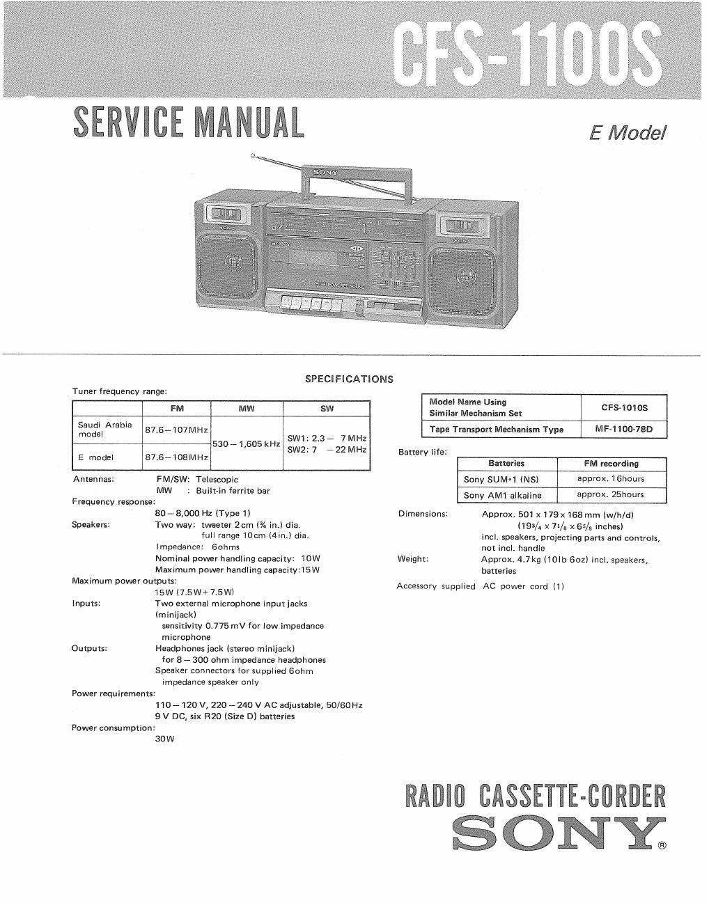
Sony cfs 1100 s service manual

This is the 18 pages manual for sony cfs 1100 s service manual.
Read or download the pdf for free. If you want to contribute, please mail your pdfs to info@audioservicemanuals.com.

Page: 1 / 18
left right
sony cfs 1100 s service manual

Extracted text from sony cfs 1100 s service manual (Ocr-read)


Page 1

E Model

Tu ner frequency range:

SPECIFICATIONS

FM MW SW
fixjeIArabia 87i6~107MHz sw1- 23- 7M:
E model 87.6-108MHz 530~ L605 kHz SW2: 7 _ 22 MHZ

Antennas: FM/SW: Telescopic

Frequency response:

Speakers:

Inputs:

Outputs:

Power requirements:

Power consu mption:

MW

. Built-in ferrite bar

80~8,000 Hz (Type 1)
Two way: tweeter 2cm (/4 int) dial

full range 1081'" Min.) diet
Impedance: Gohms
Nominal power handling capacity: 10W
Maximum power handling capacity215W
Maximum power outputs:
15W (75W+7i5Wl
Two external microphone input jacks

(minijack)

sensitivity 0.775 mV for low impedance

microphone
Headphones jack (stereo minijackl

for 8 _ 300 ohm impedance headphones
Speaker connectors for supplied Bohm

impedance speaker only

110 - 120 V, 220 - 240 V AC adjustable, 50/60 Hz
9 V DC, six R20 (Size D) batteries

30W

Model Name Using
Similar Mechanism Set CPS-1 01 OS
Tape Transport Mechanism Type MF-1100-78D
Battery life:
Batteries FM recording
Sony sumq (NS) approx, lGhours
Sony AM1 alkaline approx, 25h0ur5
Dimensions: Approx 501 x 179x 168 mm (w/h/d)
(193/4 x 71/; x 65/5 inches)
incl. speakers, projecting parts and controls,
not incl. handle
Weight: Approx. 4.7kg (10Ib 602) incl. speakers,

Accessory supplied

batteries

AC power cord (1)

WIN CASSETTE-CBRDER

ONY;

Page 2

CFS-11OOS

TABLE OF CONTENTS

Section Title Page
Specifications ....................... 1
MODEL IDENTIFICATION .............. 2
SERVICING NOTES ................... 2
SECTION 1. GENERAL ..................... 3

SECTION 2. DISASSEMBLY AND SETTING
2-1. PRE-CAUTION FOR REAR CABINET

SETTING .......................... 4
2-2. CASSETTE HOLDER REMOVAL

AND SETTING ..................... 4
2-3. TUNING KNOB REMOVAL AND

SETTING .......................... 4
2-4. POINTER SETTING ............... 5

MODEL IDENTIFICATION
- Dial Scale -

E model

FM 88 9| 94 97 IOO I03 |06
-

Saudi Arabia model

Section Title Page

SECTION 3. MECHANICAL ADJUSTMENTS - - . 6

SECTION 4. ELECTRICAL ADJUSTMENTS ..... 7

SECTION 5. DIAG RAMS

5-]. IC BLOCK DIAGRAMS ............... 9
5-2. PRINTED WIRING BOARDS ......... 10
5-3. SCHEMATIC DIAGRAM ............. 13
SECTION 6. EXPLODED VIEWS ............. 15
SECTION 7. ELECTRICAL PARTS LIST ....... 20

SERVICING NOTES

Note for Main Mounted Board Replacement
Replacement part of main mounted board is set
for E model.

When replacing main mounted board of Saudi
Arabia model, change the parts as shown below.

E model

Ref. No. (replacement part) Saudi Arabia model

ceramic capacitor ceramic capacitor

68 229E (1-102-959-00) BODF (1-102-603-00)

SAFETY-RELATED COMPONENT WARNING! I

COMPONENTS IDENTIFIED BY MARK A OR DOTTED
LINE WITH MARK A ON THE SCHEMATIC DIAGRAMS
AND IN THE PARTS LIST ARE CRITICAL TO SAFE
OPERATION. REPLACE THESE COMPONENTS WITH
SONY PARTS WHOSE PART NUMBERS APPEAR AS
SHOWN IN THIS MANUAL OR IN SUPPLEMENTS PUB-
LISHED BY SONY.