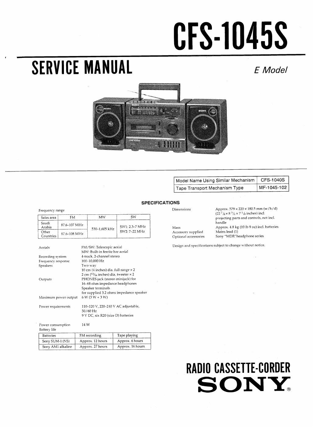
Sony cfs 1045 s service manual

This is the 23 pages manual for sony cfs 1045 s service manual.
Read or download the pdf for free. If you want to contribute, please mail your pdfs to info@audioservicemanuals.com.

Page: 1 / 23
left right
sony cfs 1045 s service manual

Extracted text from sony cfs 1045 s service manual (Ocr-read)


Page 1

[IFS-10458

SERVICE MANUAL EMoae/

Model Name Using Similar Mechanism CFS-104OS

Tape Transpon Mechanism Type MF-1045-102
SPECIFICATIONS
Frequency range Dimensions Approx. 579 x 220 x 180 5 mm (w/h/d)
, (22 7/ a 3/: x 71/» inches) incl.
53' 5 M M W projecting pans and controls, not incl.
Saudi s handle
, 8/.6-107 MHz
Arab 530-1505 kHz 5W1; 1-3-7 MHZ Mass Approx. 4.8 kg (10 lb 9 oz) incl. balIeries
0 _ S7.6~108 MHZ 5W1 7-22 MHZ Accessory supplied Mains lead (I)
C"55 Optional accessories Sony MDR"headphone series
Aerial. FM /5w; Telescopic mm Design and specifications subieei io change Wilhoul notice.
MW: Buillrin ferrite bilr aerial
Recording syslcm J-Irack, Z-channel stereo
Frequency response loo-10,000 Hz
Speakers Two way

IO cm (4 inches) dia. lull range x 2

2 cm (3/u. inches) din. tweeler X 2
Outputs PHONES jack lsiereo miniiack) {or

I6-68 olim impedance headphones

Speaker terminals

Inr supplied 3.2 ohms impedance speaker
Maximum power output 6 W (3 \V 4 3 W)

Power requirements 110-120 V, 2207240 V AC adlustable,
50/60 Hz
9 V DC, six R20 (size D) balleries
Power consumpiion 14 w
Battery life
Batlcries FM recording Tape playing
Sony SUM-1(NS) Approx. 12 hours Approx. 6 hours
Sony AMI alkaline Approx. 27 hours Approx. 16 hours

llAlllll cAssmE-collnili
SONY;

Page 2

TABLE OF CONTENTS

Section Title Page
Specifications .................................. 1

1. GENERAL

Location and Function of Controls ---------- 3

2. DISASSEMBLY ------------------------- 4

3. ADJUSTMENTS

3-1. Mechanical Adjustments ------------------- 7
3-2. Electrical Adjustments ~~~~~~~~~~~~~~~~~~ 7
Tape Section ............................. 7
Tuner Section --------------------------- 8

4. DIAGRAMS

4.], Block Diagram ........................... 10
4-2. Primed Wiring Boards --------------------- 14
4-3. Schematic Diagram --------------- 17
5. EXPLODED VIEWS ------------------- 21
6. ELECTRICAL PARTS LIST ----------- 26

SAFETY-RELATED COMPONENT WARNINGII

COMPONENTS IDENTIFIED BV MARK £\ OR DOTTED
LINE WITH MARK A ON THE SCHEMATIC DIAGRAMS
AND IN THE PARTS LIST ARE CRITICAL TO SAFE
OPERATION. REPLACE THESE COMPONENTS WITH
SONY PARTS WHOSE PART NUMBERS APPEAR AS
SHOWN IN THIS MANUAL OR IN SUPPLEMENTS PUBv
LISHED BY SONY.