Sony cfs 1025 l service manual

This is the 20 pages manual for sony cfs 1025 l service manual.
Read or download the pdf for free. If you want to contribute, please mail your pdfs to info@audioservicemanuals.com.

Page: 1 / 20
left right
sony cfs 1025 l service manual

Extracted text from sony cfs 1025 l service manual (Ocr-read)


Page 1

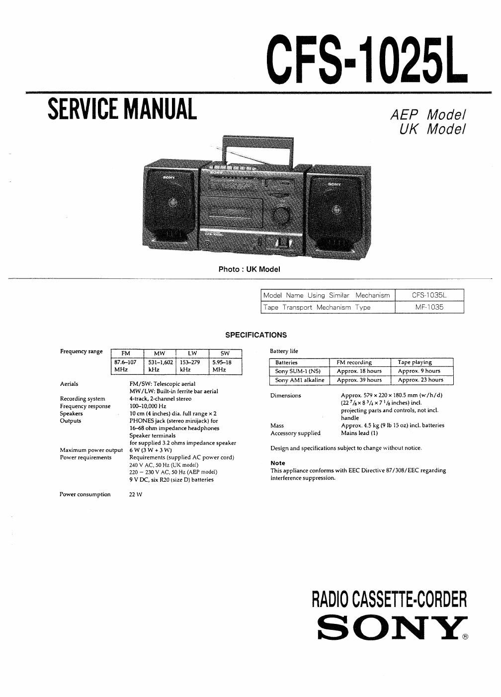
CFS-1025L

SERVICE MANUAL AEP Model

UK Model

Photo : UK Model

Model Name Using Similar Mechanism CFS-IOSSL
Tape Transport Mechanism Type MF»i 035
SPECIFICATIONS
Frequency range FM MW I LW SW Battery life
87.6-107 5314.602 153-279 5.95-18 aaiieries FM recording Tape playing
MHZ kHz kHz MHZ Sony SUM-1(NS) Approx. 18 hours Approx. 9 hours
Aerials FM/SW: Teleseopic aerial Sony AM] alkaline Approx, 39 hours Approx. 23 hours
. MW/LW: Bum {mm 6 "al Dimensions Approx. 579 x 120 x 130.5 mm (w/ii/d)
Recording system 4-mck, Z-channel stereo 22 7 8 3/ 7 / , h . I
Frequency response inc-10,000 Hz I ,/9_ " 3 " I ~ .
Speakers 10 em (4 inches) diar full range x 2 proeding parts and controls, not incl.
Outpuls PHONES jack (stereo minijack) for and _ _
16-68 ohm impedance headphones Mass Approx. 45 I150? lb I: 02) incl. baileries
Speaker terminals Accessory supplied Mains lead (1)
for supplied 3.2 ohms impedance speaker _ _
Maximum POW?! output 5 w (3 w + 3 w) Design and specifications subject lo change Without notice.
Power requiremenls Requirements (supplied AC power cord)
240 V AC, 50 Hz (UK model) Note
no _ 230 V AC_ 50 Hz (Aap model) This appliance 9 v Dc, six R20 (size D) batteries interference suepression-
Power consumption 22 W

RADIOCASSETTE-CORDER
S ONY;

Page 2

TABLE OF CONTENTS

Section Title Page
Specifications ............................................................ 1
1. GENERAL

Location and Function of Controls -------------------------------- 3
2. DIAL POINTER INSTALLATION ------------------------------ 4

3. ADJUSTMENTS

3-1. Mechanical Adjustments .
32. Electrical Adjustments

4. DIAGRAMS

4-1, Circuit Boards Locatio -
4-2, Printed Wiring Boards
4-3i Schematic Diagram -

5. EXPLODED VIEWS

5-1. General Section (1) ~
5-2. General Section (2) -
5-3. Mechanism Section (1)-~
5-4. Mechanism Section (2)--


~19
-~-20
.21

s. ELECTRICAL PARTS LIST ----------------------------------- 22

I HOW TO CHANGED THE CERAMIC FILTERS
This model is used three ceramic filters of CFl, CFZ and CF}
You must used same type of color marked ceramic filters in
order to meet same specifications
Therefore, the ceramic filter must changed three pieces
together since its supply three pieces in on package as
a spare pans.

mark mak Mark frggiigiicy
@ red 10,7OMl-lz

- blue 10,67MHZ

orange 10.73MHZ

I I black 10.64MHZ

white 10.76Ml-lz

SAFETY-RELATED COMPONENT WARNINGI!

COMPONENTS IDENTIFIED BV MARK A OR DOTTED
LINE WITH MARK A ON THE SCHEMATIC DIAGRAMS
AND IN THE PARTS LIST ARE CRITICAL TO SAFE
OPERATION. REPLACE THESE COMPONENTS WITH
SONY PARTS WHOSE PART NUMBERS APPEAR AS
SHOWN IN THIS MANUAL OR IN SUPPLEMENTS PUB-
LISHED BY SONY.