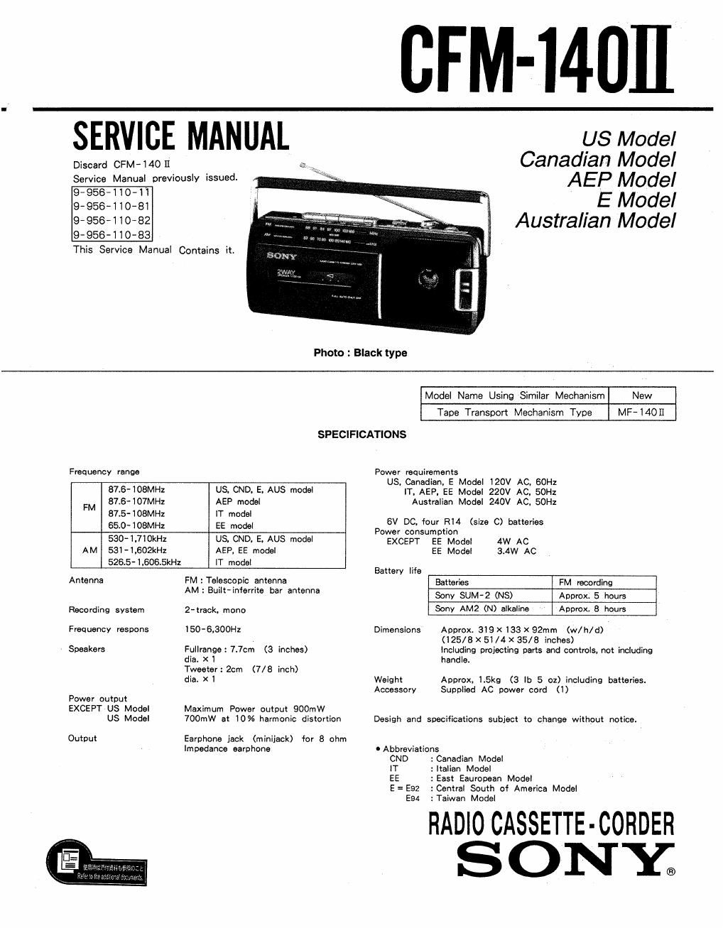
Sony cfm 140 mk2 service manual

This is the 28 pages manual for sony cfm 140 mk2 service manual.
Read or download the pdf for free. If you want to contribute, please mail your pdfs to info@audioservicemanuals.com.

Page: 1 / 28
left right
sony cfm 140 mk2 service manual

Extracted text from sony cfm 140 mk2 service manual (Ocr-read)


Page 1

CFM-i4DII

SERVICE MANUAL us Model

Discard CFM-MO 11 Canadian Model
Service Manual previously issued. AEP Model

9-956410-11
9-956-110-81 _ E Made,
9'956-110'82 Austral/an Model
9~956-110-83

This Service Manual Contains it.

Photo : Black type

Model Name Using Similar Mechanism New
Tape Transport Mechanism Type MF-14OII

SPECIFICATIONS
Frequency range Power requirements
US. Canadian. E Model 120V AC. 60H:
87-8-108MH2 U3 CND. E, AUS model 1T, AEP, EE Model 220v AC, 5on
FM 87.6-IO7MHZ AEP model Australian Model 240V AC, 50Hz
87.5-108MH1 IT model .
65.0-108MH: EE model 6V DC, four I314 (5:26 C) batteries
Power consumption
530-I.7IOI

AM 53I-I.602kHz AEP, EE model EE Model 3.4W AC
526.5-1,606.5kHz IT model
Battery lite
Antenna FM : Telescopic antenna Batteries FM recording
AM: Built-informs bar antenna Sony SUM-2 (NS) Approx. 5 hours
Recording system 2-track. mono Sony AM2 (N) alkaline Approx. 8 hours
Frequency respons 150-6,300Hz Dimensions Approx. 319 X 133 X 92mm (w/h/d)
(l25/8 X 5i /4 X 35/8 inches)
Speakers Fullrange: 7.7cm (3 inches) Including projecting parts and controls, not including
die. X 1 handle.
Tweeter: 2cm (7/8 inch)
dia. X1 Weight Approx, 1.5kg (3 lb 5 oz) including batteries.
Accessory Supplied AC power cord (1)
Power output
EXCEPT US Model Maximum Power output 900mW
US Model 700mW at 10% harmonic distortion Desigh and specifications subject to change without notice.
Output Earphone jack (minijack) for 8 ohm
impedance earphone 0 Abbreviations
CND :Canadian Model
lT : Italian Model
EE :East Eauropean Model

E= E92 :Central South of America Model
E94 :Taiwan Model

RADIO CASSETTE-CORDER
ONY;

Page 2

CFM- 14011 I

TABLE OF CONTENTS
w Elli! 382
1, GENERAL .......................................... 3
2. DISSASEMBLY ..................................... 4

3. ADJUSTMENTS
3-1. Mechanical Adjustments and Measurements-~-~ 5


3-2. Electrical Adjustments .......................... 5
LDIAGRAMS
4-1 Semiconductor Lead Layouts ------------------- 8
4-2. IC Block Diagram ............ , 8
4-3. Printed Wiring Boards (TYPE l)~ 9
4-4. Schematic Diagram (TYPE I) ................ 11
4-5. Printed Wiring Boards (TYPE H) ------------- 13
4-6. Schematic Diagram (TYPE ll) ---------------- 15
5. EXPLODED VIEWS
5- 1. Front Cabinet Assembly ----------------------- 17
5-2. Rear Cabinet Assembly ........ 4. 18
5-3. Mechanism Deck Assembly (1) ~~~~~~~~~~~~~~~~ 19
5-4. Mechanism Deck Assembly (2) ~~~~~~~~~~~~~~~~ 20
6. ELECTRICAL PARTS LIST
6 1. Electrical Parts List (TYPE I) --------------- 21
6-2. Electrical Parts List (TYPE 11) ~~~~~~~~~~~~~~~ 24
~MODEL IDENTIFICATION-
(Specification Label)
- US. CND. E Model :AC: 120V 60Hz 4W
Australian Model :AC: 240V~50Hz 4W

AEP, Italian. EE Model :AC: 220V~50Hz 4W

SONY.
MODEL N0. ch- 140 u

RADIO CASSETTE-CORDER
WWW]
DC: 6V FLASHLITE BATTERY

W

TYPE I :MADE IN TAIWAN.Fi.O.C.
MADE IN MALAYSIA

TYPE I] : SONY CORP.
Applicable Serial No.
US Model : 500,001 and later.
E Model: 500,001 and later.
0 Abbreviations
CND: Canadian Model
E= E92: Central South of America Model
EsazTaiwan Model
EE :East European Model

SAFETY CH ECK-OUT

After correcting the original service problem,
perform the following safety check before releasing
the set to the customer:

Check the antenna terminals, metal trim, metallized
knobs, 'screws, and all other exposed metal parts for
AC leakage. Check leakage as described below.

LEAKAGE TEST

The AC leakage from any exposed metal part to
earth ground and from all exposed metal parts to any
exposed metal part having a return to chassis, must
not exceed 0.5 mA (500 microampers). Leakage
current can be measured by any one of three
methods.

1. A commercial leakage tester, such as the
Simpson 229 or RCA WT-S40Ar Follow the
manufacturers instructions to use these instru-
ments.

2. A battery-operated AC milliammetcr. The Data
Precision 245 digital multimeter is suitable for
this job.

3. Measuring the voltage drop across a resistor by
means of a VOM or battery-operated AC volt-
meter. The limit indication is 0.75 V, so
analog meters must have an accurate low-
voltage scale: The Simpson 250 and Sanwa
SH-63Trd are examples of a passive VOM that
is suitable. Nearly all battery operated digital
multimeters that have a 2V AC range are
suitable. (See Fig. A)

To Exposed Metal
Pairs on Set

0-75MF I 1.51:0

'._l

"7' Earth Ground

A C
voltmeter
(0. 75 V}

Fig. A. Using an AC voltmeter to check AC leakage.

(US, Canadian Model)