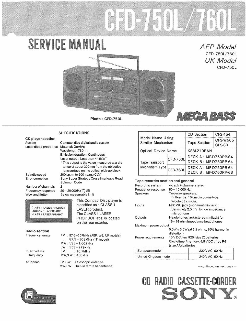
Sony cfd 760 l service manual

This is the 65 pages manual for sony cfd 760 l service manual.
Read or download the pdf for free. If you want to contribute, please mail your pdfs to info@audioservicemanuals.com.

Page: 1 / 65
left right
sony cfd 760 l service manual

Extracted text from sony cfd 760 l service manual (Ocr-read)


Page 2

CFD-750L/760L

Power consumption 35 w
Battery life
. FM continuous
Batteries recording Playback
Sony SUM-1 (NS) Approx. 9 hours Approx. 4 hours
Sony AM-1 (N)
alkaline Approx. 16 hours Approx. 8 hours

Forclockltimerlrnemory: Approx. 1 year

Dimensions 696 x255 x 236 mm (w/h/d)
(27'/2 x 10ls x 93/8 inches)
not incl. projecting parts and controls
Weight Approx. 9.4kg, incl. batteries
(Approx. 20 lb 12 oz)
Supplied accessory AC power cord (1)
Remote commander RMT-C760 (1)
(for CFD-760L only)

Design and specifications subject to change without notice.

Note
This appliance conforms with EEC Directive 87/308/EEC regarding
interference suppression.

Memory preset tuning
A total of 20 stations can be stored in any order

High quality sound

0 The Sony MEGA BASS system produces a powerful bass.

0 By pressing the SPACE SOUND button, depth and
spaciousness can be added to the original sound.

A high performance, high fidelity CD player with

many functions

0 An 8 cm (3-inch) CD can be played without using an
adaptor.

0 Repeat function allows playing either the entire disc or a
single selection.

- Program play for playing selections in the order desired.

- Shuttle play for playing selections repeatedly in random
order.

O A synchronized CD starting system for recording.

0 An automatic editing function-The CD player automati-
cally edits the selections on a CD depending on the tape
length.

Digital clock timer

0 You can listen to CD, radio or ataped program (for
CFD-760L only) at a preset time.

0 You can record CD or radio programs at a preset time.
(for CFD-760L only)

Others
0 High or normal speed tape dubbing
o CFD-760L are supplied with a remote commander.

TABLE OF CONTENTS

Section Title Page

1.

2.
2-1.
2-2.

3.

3-1.
3-2.
3-3.
3-4.

4.

5.

5-1.
5-2.
5-3.

6.

6-1.
6-2.
6-3.
6-4,
6-5.
6-6.
6-7.
6-8.
6-9.

6-10. Semiconductor Lead Layout ~~~~~~~~~~~~~~~

7.

7-1.
7-2.
7-3.
7-4.
7-5.
7-6.
7-7.
7-8,
7-9.

8.

SERVICING NOTES ............................................. 3

GENERAL
Parts Indentification ~~~~~~~~~~~~~~~~~~~~~~~~~~~~~~~~~~~~~~ 4
Setting the Clock ................................................... 6

DIS ASSEMBLY
Cabinet (Front) Assy ............................................. 7
Cabinet (Upper) Assy~ " ~
MD Assy (DECK A) -
MD Assy (DECK B)


MECHANICAL ADJUSTMENTS ------------------------------ 9

ELECTRICAL ADJUSTMENTS

Tape Recorder Section ....................................... 10
Radio Section -
CD Section


DIAGRAMS
Circuit Board Location
Block Diagram -Main Section
Block Diagram *CD Section-u
Printed Wiring Board -Main Section-
Schematic Diagram ~Main Section-
Schematic Diagram -Power Section- ~
Schematic Diagram -CD Sectionm
Pristed Wiring Board -CD Section-~~~
Schematic Diagram -Tuner Sectioni ~

EXPLODED VIEWS
Cabinet Section ~
CD Block Assy ~
Rear Cabinet Section
Speaker Box Section
Optical Block ~~~~~~~~~~~~~
Mechanism Section (1)
Mechanism Section (2)
Mechanism Section (3)
Mechanism Section (4)

ELECTRICAL PARTS LIST

SAFETY-RELATED COMPONENT WARNING

COMPONENTS IDENTIFIED BV MARK A DR DOTTED
LINE WITH MARK A ON THE SCHEMATIC DIAGRAMS
AND IN THE PARTS LIST ARE CRITICAL T0 SAFE
OPERATION. REPLACE THESE COMPONENTS WITH
SONY PARTS WHOSE PART NUMBERS APPEAR AS
SHOWN IN THIS MANUAL OR IN SUPPLEMENTS PUB-
LISHED BY SONY.