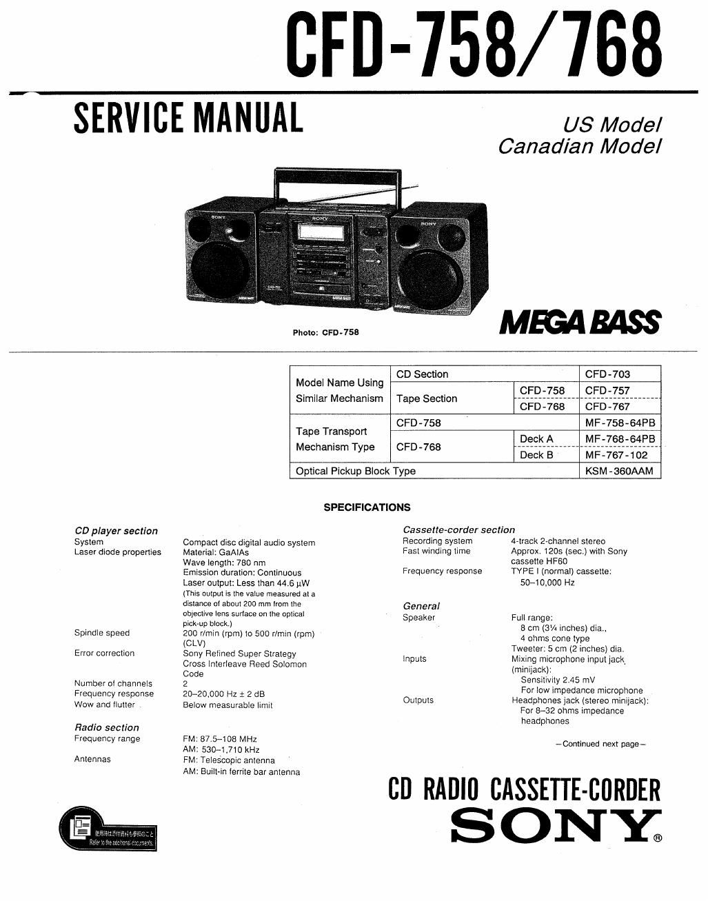
Sony cfd 758 service manual

This is the 70 pages manual for sony cfd 758 service manual.
Read or download the pdf for free. If you want to contribute, please mail your pdfs to info@audioservicemanuals.com.

Page: 1 / 70
left right
sony cfd 758 service manual

Extracted text from sony cfd 758 service manual (Ocr-read)


Page 1

CFD-758/ 768

SERVICE MANUAL

US Model
Canadian Model

MEGAMSS

Photo: CFD - 758

. CD Section CPD-703
Model Name Using ' C FD-758 C F915] _______
Similar Mechanism Tape Section CFD-768CFD-767
CFD-758 MF-758-64FB
Tape Temp Deck A 7 mews-64351
Mechanism Type CFO-768 Deckla; vvvvv ililIVF-767-102
Optical Pickup Block Type KSM -360AAM

SPECIFICATIONS

CD player section
System
Laser diode properties

Spindle speed
Error correction
Number ol channels

Frequency response
Wow and flutter

Radio section
Frequency range

Antennas

Compact disc digital audio system
Material: GaAlAs

Wave length: 780 nm

Emission duration: Continuous
Laser output: Less than 4415 pW
(This output is the value measured at a
distance at about 200 mm lrorn the
objective tens surlace on Ihe optical
pick-up block.)

200 rlmin (rpm) to 500 rlmin (rpm)
(CLV)

Sony Relined Super Strategy
Cross interleave Reed Solomon
Code

2

20-20000 Hz 1 2 dB

Below measurable limit

FM: 87.5-108 MHZ

AM: 530-4710 kHz

FM: Telescopic antenna

AM: Built-in lerrite bar antenna

Cassene-corder sect/an

Recording system
Fast winding time

Frequency response

General
Speaker

inputs

Outputs

4-track 2»channe| stereo

Approx. 120s (sec) with Sony

cassette HF60

TYPE | (normal) cassette:
50-10000 Hz

Full range:
8 cm (3% inches) dia..
4 ohms cone type
Tweeter: 5 cm (2 inches) dia.
Mixing microphone input jack
(minijack):
Sensitivity 2.45 mV
For low impedance microphone
Headphones jack (stereo minijack):
For 8-32 ohms impedance
headphones

~Cominued next page-

cn RADIO CASSETTE-BORDER
S ON E

Page 2

Power output 10 W + to W (at 4 ohms. 10 %
(excluding US model) harmonic distortion in DC operation)
Power requirements For CD radio cassette-comer:

120 V AC, 60 Hz (Other models)

12 V DC. 8 size D (R20) batteries
For clock/timer/memory:

6 V DC. 4 size AA (R6) batteries
For remote commander:

3 V DC. 2 size AA (R6) batteries

Power consumption 43 W (Canadian model)

40 W (Other models)
Battery lite For 00 radio cassette-corder:
FM recording Tape playback CD playback
Sony SUM-l (NS) approx. 4 h approx. 2 h approx. 1 h

Sony Alkaline AMI approx. 12 h approx. 5.5 h approx. 3 h

For clock/timer/memory:
approx, 1 year
For remote commander:
approx. 6 months
Dimensions 633 x 208 x 246 mm (w/h/d)
(25 x 8% x 9% in.) (incl, protecting
parts and controls)

Mass 9.5 kg (20 lb. 15 oz.)
(incl, batteries)
Supplied accessories AC power cord (1)

Remote commander (1)

Design and specifications subject to change without notice.

TABLE OF CONTENTS

Section M Egg;
1. GENERAL
Looking at the Controls .................. . .............. 4
Connecting the Speakers ................................. 5
Choosing Power Sources ................................. 6
Setting the Clock ---------
Selecting the Audio Emphasis ~~~~~~~~~~~~~~~~~

Listening to the Radio
Presetting Radio Stations

Playing Preset Radio Stations
Playing a CD (normal play) -~

Playing Specific Tracks ~~~~~~~~~~~~~~~~
Playing the Beginning of Each Track (intro scan) '-
Playing Tracks in Random Order (shuffle play) ~~~~~~~~~~ 9
Playing Tracks in the Desired Order
(program play) --------------- 10
Playing Tracks Repeatedly ~~~~~ 10
Checking and Changing Track Order 11
Playing a Tape .............. 11
Recording From the Radio 12
Recording From Another Tape (dubbing) 12
Recording 3 CD ........................ 13
Recording a CD : Specifying Track Order ~ 13
Recording a CD : Specifying Tape Length ~ 14
Falling Asleep to Music ~~ 14
Waking Up to Music 15
(CPD-768 Only) Timer-Recording Radio Programs 15
Setting Up a P_A System ............... . ........ 16
2. DISASSEMBLY ~~~~~~~~~~~~~~~~~~~~~~~ . ~~~~~~~~~~~~~~~~ t7
3. MECHANICAL ADJUSTMENTS ~~~~~~~~~~~~~~~~~~~~~~ Z7
4. ELECTRICAL ADJUSTMENTS ~~~~~~~~~~~~~~~~~~~~~~ Z7

5. DIAGRAMS
51. 1C801 (CXP50716056Q) Pin Function Description 32
52 Block Diagram ~~~~~~~~~ 33


53. Circuit Boards Location -- 36
54. Printed Wiring Board -Tuner Section- ~~ 37
55. Schematic Diagram -Tuner Section- ~- 39
56. Printed Wiring Board -CD Section -- 42
57. Schematic Diagram -CD Section- ~ 45
58. Printed Wiring Board -Main Section - 50
59. Semiconductor Lead Layouts -- -- 54
5-10. Schematic Diagram -Main Section- ~ 55
5-11. Printed Wiring Board Control Section- ~~~~~~~~~~ 60
512. Schematic Diagram -Control Section- ~~~~~~~~~~~~~ 63
5-13.1C Block Diagrams ~~~~~~~~~~~~~~~~~~~~~~~~~~~~~~~~~ 64
6. EXPLODED VIEWS

61. Rear Cabinet Section

6-2. Front Cabinet Section ~
63. Upper Cabinet Section (CFD~758) ~~~~~~~~~~~~~~~~~ 69
6-4. Upper Cabinet Section (CFD-768) ~~~~~~~~~~~~~~~~~~ 70
65. Mechanism Deck Section'l 63. Mechanism Deck Section-2 (CFD-758) ~~~~~~~~~~~~~~~ 72
GT Mechanism Deck Section-3 (CFD-758) -------------- 73
68. Mechanism Deck Section-4 (CPD-758) ~~~~~~~~~~ 74
69. Mechanism Deck Section-5 (CFDv768) ~

610. Mechanism Deck Section-6 (CFD-768)
6»11.Mechanism Deck Sectionfl (CFD-768)~ '~
5-12. Mechanism Deck Section-8 (CFDv768) -------------- 79


6-13 CD Chassis Section ................................. 80
644. Optical Pickup Section ~~ 81
645. Speaker Box Section (CFD-758) ~ .. 82
616. Speaker Box Section (CFD-768) ~~~~~~~~~~~~~~~~~~~ r 83

7. ELECTRICAL PARTS LIST ~~~~~~~~~~~~~~ ~~~~~~~~~ 98

__2_