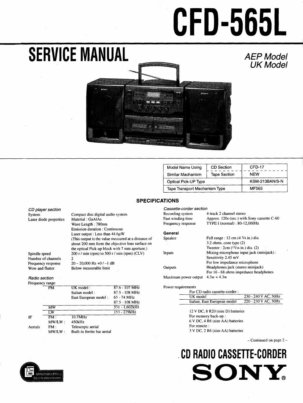
Sony cfd 565 l service manual

This is the 35 pages manual for sony cfd 565 l service manual.
Read or download the pdf for free. If you want to contribute, please mail your pdfs to info@audioservicemanuals.com.

Page: 1 / 35
left right
sony cfd 565 l service manual

Extracted text from sony cfd 565 l service manual (Ocr-read)


Page 2

AC 28 W

For CD radio cassette-corder :

FM Iecordin

Sony RZOP : approx. II h

Sony alkaline LRZO : approx. 16 h
Tape playback

Sony R20? : approx. 6 h

Sony alkaline LR20 I approx. IO II
CD playback

Sony R20? '. approx. 4 h

Sony alkaline LRZO : approx. 6 h

Power consumption
Battery Life

Dimensions Approx. 653 x 267 x 207 mm ( w / h l d )
(25 l X 105/l X 8/ inches) (incl. projecting parts)
Mass Approx. I IS kg (24 lb. l5 oz) (incl. batteries)
Supplied accessory AC power cord (I)

Remote controller ( I)

Design and specifications are subject to change without notice.

DANGER
Invisible laser radiation when open and interlock failed or defeated.
Avoid direct exposure to beam.

CAUTION

Use of controls or adjustments or performance of procedures other»

than those specified herein may result in hazardous radiation expo-
sure.

Information
Laser component in this product is capable of emitting radiation ex-
ceeding the limit for Class I.

For customers in Europe

This Compact Disc player is
classified as aCLASS I LASER
product.

The CLASSLASER
PRODUCT label is located on
the side.

CLASS I LASER PRODUCT

LUOKAN 1 LASERLAITE
KIASS 1 LASERAPPAFIAT

Flexible Circuit Board Repairing

° Keep the temperature of the soldering iron around 270°C during
repairing.

' Do not touch the soldering iron on the same conductor of the cir-
cuit board (within 3 times).

0 Be careful not to apply force on the conductor when soldering or
unsoldering.

Notes on chip component replacement

- Never reuse a disconnected chip component.

' Notice that the minus side of a tantalum capacitor may be dam-
aged by heat.

SAFETY-RELATED COMPONENT WARNINGII

COMPONENTS IDENTIFIED BY MARK A 0R DOTTED LINE
WITH MARK AON THE SCHEMATIC DIAGRAMS AND IN THE
PARTS LIST ARE CRITICALTO SAFE OPERATION. -
REPLACE THESE COMPONENTS WITH SONY PARTS WHOSE
PART NUMBERS APPEAR AS SHOWN IN THIS MANUAL OR IN
SUPPLEMENTS PUBLISHED BY SONY.

TABLE OF CONTENTS
Specifications ................................................................................. l
1. SERVICING NOTES ......................................................... 3
2. GENERAL
Location and Function of Controls .......................................... 4

3. ADJUSTMENTS
3-I. Mechanical Adjustments.
3-2. Electrical Adjustments

4. EXPLANATION OF IC TERMINALS ......................... ll

5. DIAGRAMS
5-1. Circuit Boards Location
5-2. Printed Wiring Boards ~ Main Section -
5-3. Schematic Diagram - Main Section -
5-4. Printed Wiring Boards - CD Section -
5-5, Schematic Diagram - CD Section <


6. EXPLODED VIEWS
6-] , Rear Cabinet Section
6-2. Front Panel Section
6-3. CD Cabinet Section .
6-4. Mechanism Deck Section (I
6-5. Mechanism Deck Section (2
6-6. Optical Pick-up Section
6-7. Speaker Section

7. ELECTRICAL PARTS LIST 38