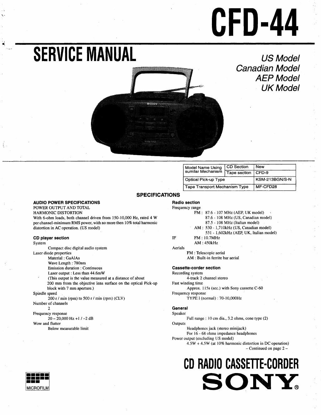
Sony cfd 44 service manual

This is the 44 pages manual for sony cfd 44 service manual.
Read or download the pdf for free. If you want to contribute, please mail your pdfs to info@audioservicemanuals.com.

Page: 1 / 44
left right
sony cfd 44 service manual

Extracted text from sony cfd 44 service manual (Ocr-read)


Page 2

Power requirements
120 V AC. 60Hz.: US, Canadian model
220 - 230 V AC, SOHZ : AEP, Italian model
230 ~ 240 V AC, 50H: : UK model
12V DC, 8 size D (R20) batteries
Power consumption
AC 25 W , .
Battery Life
Whig-
Sony R20? : approx 9 h
Sony alkaline LRZO : approx. 18 h
Tape playback
Sony RZOP : approx. 5 h
Sony alkaline LRZO : approx. 9 h
CD playback
Sony RZOP : approx) 3.5 h
Sony alkaline LRZD : approx. 7 h

Dimensions
Approx. 400 x 173 x 244 mm (w/h/d)
(153/. X 67/) X 95/; inches) (incl. projecting parts)
Mass
Approx. 4kg (8 1h 13 oz) (incl. batteries)
Supplied accessory .
AC power cord (1)
Design and specifications are subject to change without notice.

CAUTION

Use of controls or adjustments or performance of procedures other
than those specified herein may result in hazardous radiation expo-
SUIC.

Laser component in this product is capable of emitting radiation
exceeding the limit for Class 1.

For customers in Europe

This Compact Disc player is
classified as aCLASS 1 LASER
product.

The CLASS 1 LASER
PRODUCT label is located on
the rear exterior.

CLASS 1 LASER PRODUCT

LUOKAN 1 LASERLAITE
KLASS1 LASEHAFPARAT

MODEL IDENTIFICATION
- Model Number Label -

SONY.

MODEL NO. cFD-44,

//////////////////////

A0120V~60Hz : US, Canadian model
AC 220V-230VN50H2 : AEP. Italian model
AC 230VV50Hz : UK model

TABLE OF CONTENTS

Section lit-k IE
Specification ..................................................................................... l
1. SERVICING NOTES .................................................... 3
2. GENERAL -

Location and Function of Controls ............................................ 5
3. DISASSEMBLY

4.

3-]. Cabinet (Front) Removal ..
3-2. Cabinet (Upper) Removal .
3-3. CD Section Removal ..
3-4. Main BoardRemoval ..
3-5. Power Board and Transformer Board Removal .......


ooqxloat

ADJUSTMENTS
4-1. Mechanical Adjustment
4-2. Electrical Adjustment

EXPLAMNATION OF 16 TERMINALS ................... 15
DIAGRAMS
6-1. Block Diagram (Main Section) .. 17


6-2) Block Diagram (CD Section)
6-3. Circuit Boards Location ........
6-4. Printed Wiring Boards ............................
6-5. Schematic Diagram (Main (1/2) Section
6-6. Schematic Diagram (Main (2/2) Section) ..
6-7. Printed Wiring Boards (CD Section)
643. Schematic Diagram (CD Section)
6-9. 1C Block Diagram ..........

EXPLODED VIEWS
7-1 . Cabinet (Front) Section .i
7-2. Cabinet (Rear) Section
7-3. Cabinet (Upper) Section
7-4. Mechanism Deck Section -I .
7-5. Mechanism Deck Section -2.
7-6. CD Chassis Section
7«7. Optical Pick-up Section

ELECTRICAL PARTS LIST ................................................ 47