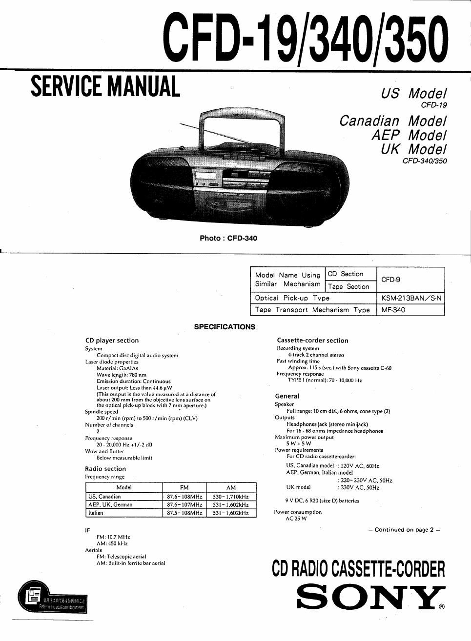
Sony cfd 340 owners manual

This is the 35 pages manual for sony cfd 340 owners manual.
Read or download the pdf for free. If you want to contribute, please mail your pdfs to info@audioservicemanuals.com.

Page: 1 / 35
left right
sony cfd 340 owners manual

Extracted text from sony cfd 340 owners manual (Ocr-read)


Page 2

Battery life
. For CB radio cassettecordet:

FM recording
Sony SUM-I (NS): approx. 3.5 1"
Sony alkaline AMI: approx. 10 h

Tape playback

Sony SUM-l (NS): approx. 1.5 h
Sony alkaline AMI: approx. 5.5 It
co pIayback

SonySUM-I (NS): approx. l h
Sony alkalineAMl: approx, 3.5 h

Dlmensions

approx. 525 x172 x 241 mm (w/h/d)

(20 Vac le9 v: inches) (incl. projecting parts)
Mass

approx. 4.5 kg (9 lb. 1-) oz) (incl. batteries)
Supplied accessory

AC power cord (1)

Remote control (RMT-CBSO) (t) (for CFD-l9/350)

Design and specifications are subject to change without
mice.


CAUTION
Use ofconlrols or adjustments or performance
of procedures other than those specified herein
may rcsull in hazardous radiation exposure.

Laser component in this product is capable of emitting
radiation exceeding the limit for Class ll

For customers in Europe

This Compact Disc player is
classified as a CLASS I LASER
product.

The CLASS I LASER
PRODUCT label is located on
the rear exlerior.

CLASS 1 LASER PRODUCT '
LUOKAN 1 LASERLAITE

_ KLASSI LASERAPPARAT

MODEL IDENTIFICATION
-- Model Number Label -

SONIo CPD-19
MODEL N0. <- CFO-340
co RADIO CASSETTE -CORDER CPD-350

///////////

AC : 120V~60HZ (US, Canadian model).
AC : 220-230V~50Hz

(AEP, German. Italian model)
AC : 230V~50Hz (UK model)


TABLE OF CONTENTS

Section Title Page
Specifications . . .. ........................................................... l
1. SERVICING NOTES ............................................... 3
2. GENERAL

Location and Function of Controls ~~~~~~~~~~~~~~~~~~~~~~~~~~~~~~~~~ 4
3. DISASSEMBLY

3-1. Cabinet (Front) Removal --5

3-2, Mechanism Deck RemovaI ~ 5

3-3, CD Cabinet Section Removal 6

3-4. Magnet, Chucking Plate Removal --6

4. ADJUSTMENTS
4-1. Mechanical Adjustments .
4-2. Electrical Adjustments

5. EXPLANATION OF IC TERMINALS ~~~~~~~~~~~~~~~~~~~~~ l3

6. DIAGRAMS
6-]. Circuit Boards Location"
6-2. Printed Wiring Boards
6-3. Schematic Diagram (Audio Section)
6-4. Schematic Diagram (Main Section) -
6-5. IC Block Diagrams

7. EXPLODED VIEWS
7-1. Front Cabinet Section
7-2. Rear Cabinet Section -~
7-3. Mechanism Deck Section (1)
7-4. Mechanism Deck Section (2)
7-5. CD Section --------------
7-6, Optical Pick-up Section


3. ELECTRICAL PARTS LIST ................................... 37