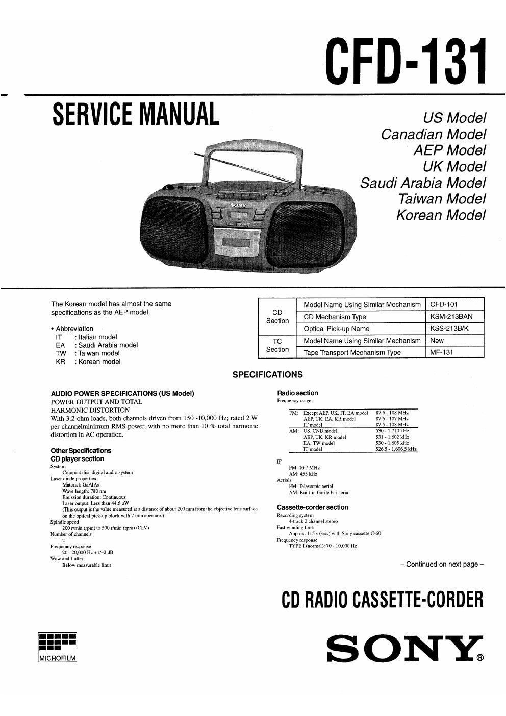
Sony cfd 131 service manual

This is the 38 pages manual for sony cfd 131 service manual.
Read or download the pdf for free. If you want to contribute, please mail your pdfs to info@audioservicemanuals.com.

Page: 1 / 38
left right
sony cfd 131 service manual

Extracted text from sony cfd 131 service manual (Ocr-read)


Page 1

CFD-131

SERVICE MANUAL

US Model
Canadian Model
AEP Model

UK Model

Saudi Arabia Model
Taiwan Model
Korean Model

The Kfiorean model haiEaFlmosgtllie same Model Name Using Similar Mechanism CPD-101
s eci cations as the mo 9.
D 86:20 CD Mechanism Type KSM-ziaBAN
0 Abbreviation Optical Pick-up Name KSS-213B/K
: I II n model . . . .
EA , StZUZi Arabia model TC Model Name Usmg Similar Mechanism New
TW 2 Taiwan model Section Tape Transport Mechanism Type MF-131
KR 2 Korean model
SPECIFICATIONS
AUDIO POWER SPECIFICATIONS (US Model) Radio section
POWER OUTPUT AND TOTAL Frequency range
HARMONIC DISTORTION FM: ExceptAEP, UK, IT. EA model 87.6 - 108 MHz
With 3.2-ohm loads, both channels driven from ISO -10,000 Hz; rated 2 W AEP, UK, EAKR mode] 87.6-107 MHz
per channelminimum RMS power, with no more than 10 % total harmonic IT mod?! 37-5 - 103 MHZ
distortion in AC operation. AM: X2153]? Wilma :3): 1:23): 11::
EA, TW model 530 - 1,605 kHz
Other Specificalions IT model 526.5- 1 506.5 kHz
CD player section [F
System FM~ lO 7 MHz
Compact disc digiui audiosysiem AM. 453 kHz
userdiodepmpenies Acmk
Male/Vi: GWA PM: Teiempic aerial

Wm Ieiiglli: 780 nm
Emission duralion: Continuous
Laser ouipui: Less nun. 44.6 uw
(This oulpul is 19 Value masund n a disunce ofaboul 200 mm fmmlhe objemlve lens surface
on are opIical pick-up block wilh 7 mm aponula.)
Spindle speed
200 r/mln (rpm) lo 500 min (rpm) (CLV)
Number of channels
2
Frequency response
20 - 20,000 Hz +ll-2 an
Wow and flulier
Below measumble iimii

MICROFILM

AM: BullI-m fenlle bar aerial

Cassetlie-oorder seclion
Recording syflem
4-xrack 2 channel norm
Fast Wmdmg um:
Approx. 5 s (m) with Sony casserle cw
Frequency response
TYPE 1 (normal): 70 -10,000 Hz

- Continued on next page -

CD RADIO CASSETTE-CORDER

ONY;

Page 2

General
Speaker
Full range: to cm an. 32 ohm. cone type (2)
Outputs
Headphones Jack (stereo minijnck)
For l6 - 63 ohms rmpcdnnca headphones
Power output (catch-ding US model)
2.3 W + 2.3 W (at 32 ohms. ID % harmonic distortion)
Power requirements
120V AC, 60 Hz (US, CND, TW model)
220 . 230 V AC, 50 Hz (AEI, IT model)
230 ~ 240 V AC. 50 Hz (UK model)
110 - 120 V120 ~ 240 V AC selectable, 50/60 Hz (EA model)
9 v Dc, 6 R20 (size D) batteries

Power consumption
ac as w (rw model)
AC 20 w (Exoepl TW model)
Battery life
For CD radio casseuecorasn
FM recordi

4-_______
Sony 1120?; approx. 13.5 in

Sony alkaline LRZO: 82 Ex. 19 II
T

Sony RZOP: aarox. 7,5 It

Sony alkaline LRZO: apgox. 12 h
CD pla

Son RZOP: a rox. 2.5 h

__L_L__-
Sony alkaline LRZO: «max. 4.5 h

Dimensions

Approx. 446x165><234 mm (Wm/n)

(17 5/: x6 m x9 1/4 inches) one]. projecting pans)
Mass

Approx. 3.9 kg (8 lb. 1001) (incl. batteries)
Supplied attessory

AC powcrcord (1)

Design and spedficflnons are subject to Change without notice.

~ Abbreviation

IT : Italian model

EA :Saudi Anhia model
CND t Canadian model
TW : Taiwan model

HOWTO CHANGETHE CERAMIC FILTERS

This model is used two ceramic filters of CH and 3.

You must use same type of color marked ceramic filters in order to
meet same specifications.

Therefore, the ceramic filter must change two pieces together since
it's supply two pieces in one package as a spare parts.

Center
mark mark mark Frequency
/// red 10.70 MHz
blue 1067 MHz
CF7 orange 10.73 MHz
black 10.64 MHz
I white 1076 MHz

This appliance is classified as
3 CLASS 1 LASER

product.

The CLASS 1 LASER
PRODUCT MARKING is
located on the rear exterior.

CLASS 1 LASER PRODUCT

LUOKAN 1 LASERLAJTE
KLASS1 LASERAPFARAT

CAUTION

Use of controls or adjustments or performance of proce-
dures other than those specified herein may result in haz-
ardous radiation exposure.

Flexible Circuit Board Repairing

- Keep the temperature of the soldering iron around 270C during
repairing.

0 Do not touch the soldering iron on the same conductor of the circuit
board (within 3 times).

I Be careful not to apply force on the conductor when soldering or
unsoldering.

Notes on Chip Component Replacement

0 Never reuse a disconnected chip component.

0 Notice that the minus side of a tantalum capacitor may be dam<
aged by heat.

NOTES ON HANDLING THE OPTICAL PICK-UP BLOCK 0R
BASE UNIT

The laser diode in the optical pick-up block may suffer electrostatic
breakdown because of the potential difference generated by the
charged electrostatic load, etc. on clothing and the human body.
During repair, pay attention to electrostatic breakdown and also use
the procedure in the printed matter which is included in the repair
parts.

The flexible board is easily damaged and should be handled with
care.

NOTES ON LASER DIODE EMISSION CHECK

The laser beam on this model is concentrated so as to be focused on
the disc reflective surface by the objective lens in the optical pick-up
block, Therefore, when checking the laser diode emission, observe
from more than 30 cm away from the objective lens,

CHUCK PLATE JIG 0N REPAIRING

On repairing CD section, playing a disc without the CD lid, use Chuck
Plate jig.
0 Code number of Chuck Plate jig : X-49l8-255»1