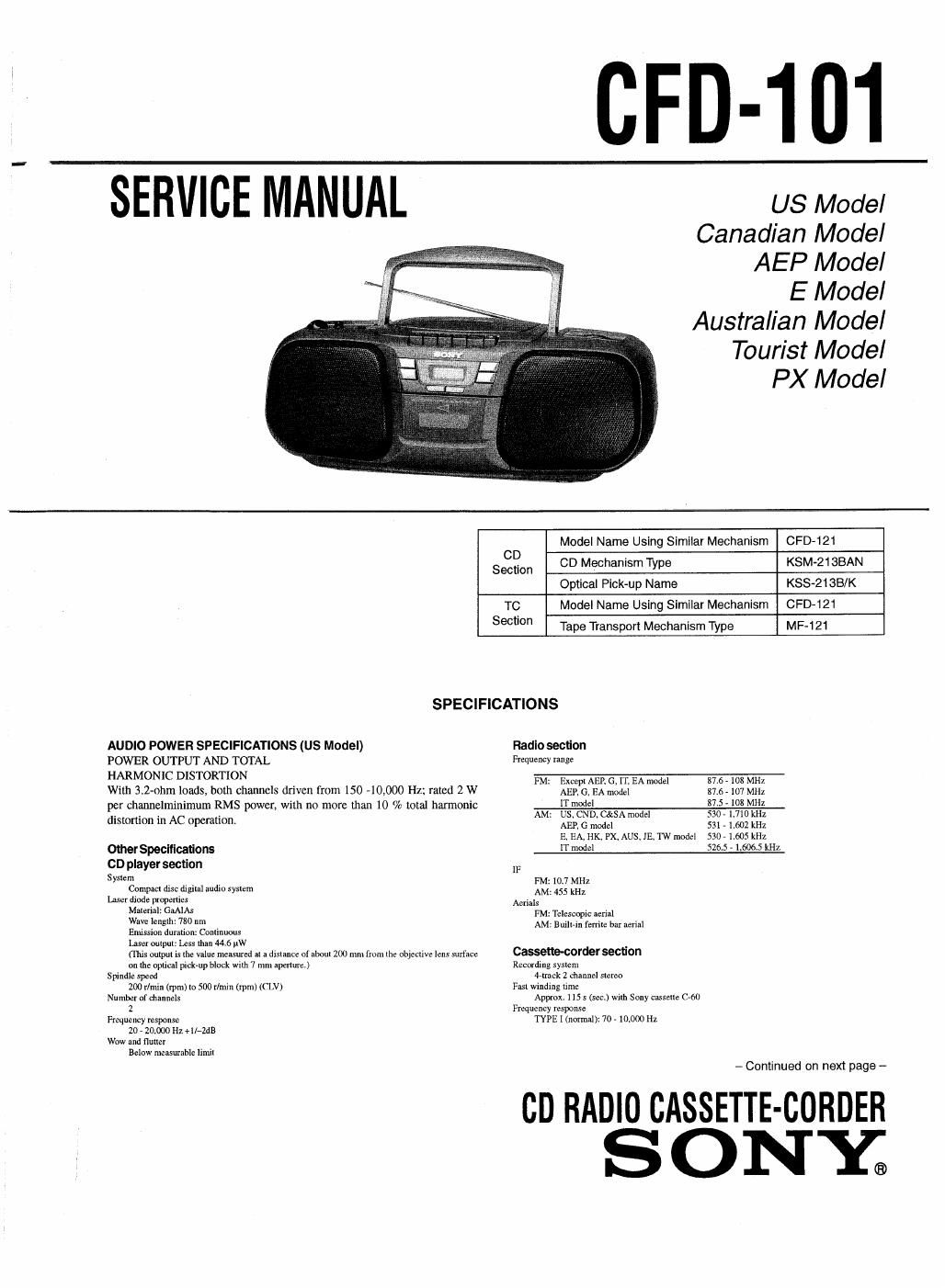
Sony cfd 101 service manual

This is the 40 pages manual for sony cfd 101 service manual.
Read or download the pdf for free. If you want to contribute, please mail your pdfs to info@audioservicemanuals.com.

Page: 1 / 40
left right
sony cfd 101 service manual

Extracted text from sony cfd 101 service manual (Ocr-read)


Page 1

CFD-101

SERVICE MANUAL

US Model
Canadian Model
AEP Model

E Model
Australian Model
Tourist Model
PX Model

Model Name Using Similar Mechanism CPD-121
S eilljio n CD Mechanism Type KSM-21 SBAN
Optical Pick-up Name KSS-ZlSB/K
TC Model Name Using Similar Mechanism CPD-121
Section Tape Transport Mechanism Type MF-121
SPECIFICATIONS
AUDIO POWER SPECIFICATIONS (US Model) Radio secfion
POWER OUTPUT AND TOTAL Frequency range
HARMON 1C DISTORTION FM: Except AER 6, 11: EA model 31.5 - 108 MHz
With 3.2-nhm loads, both channels driven from 150 40,000 Hz; rated 2 W AEP. G,EA model 37.5 I07 MHz
per channelmlnimum RMS power, with no more than 10 % total harmonic . 1T model 37 ngoIIIII-IIZ
distortion in AC operation. AM. Bagging?" model 53?: I 652 m:
E. EA, HK, Px,Aus. 15. TW mode] 530. 1.605 kHz
Olher Specificafions lT model 529.5 - 1,6065 kHz
CD player section IF
Sysm , , FM: 10.7 MHz
Compm disc dlgllall audio syalern AM; 455 kHz
Lnaer diode propenlex Ami;
mm GA'A FM: Telescopic nerinl
WY lanslhr 73° "' , AM: Bnllr-rn ierrile bar aerial
Ennsrrnn durauoll: Conllnuous
laser oulpnl: leer IIun 44.6 MW
(This oulpul is (he value measured a: a dislance or alaaln 200 mm rmn. llrr objective lens surface Cassetlecorder secllon

on lire optical pick-up block wilh 7 mm aperrure)
Spindle speed

200 r/nrin (rpm) lo 500 r/rnir. (rpm) ((LV)
Number of channelx

2
Frequency response

20 » zoiooo Hz '11»sz
Wow nnd nnner

Below measurable Ill-nil

Recording syslem
4-Irack 2 channel 51am
Fasl winding Ilm:
Approx, us 5 (son) with Sany casselle c-w
Frequency response
TYPE 1 (normal): 70 . 10.000 Hz

cn RADIO CASSETTE-CORDER
S ONYE

Page 2

General
Speaker
Full range: 10 cm dis 3.: ohms. cone type (2)
Olllpuls
Headphones Jack (stereo niinijack)
For it . 68 ohms inutedance headmtonex
Power mlpul (excluding us model)
2.3 w ¢ 2.3 w (a! 3.2 ohm, lo % harmonic distortion)
Power rcquimntems
no v AC. so Hz (Us, cup, 1w, C&SA model)
220 . 230v AC. so Hz (AEP. 6, rr model)
230 . 240 v AC. so Hz (AUS model)
1 lo , 120 v, 220 . 240v AC seleclahle 50/60 Hz (5. EA, HK, rx, IE model)
9 v m2. 6 R20 (sin n) batteries

Power consumption
AC 75 w (rw model)
AC 20 w (Except 'rw model)
Enllely IiIe
For CD radio mnehecondoi:
FM
Sony RZOP: m [35 h
Sony nlluline LRZD: nmx. l9 h
T back
Son mar: rox. 7.5 h

A...
Sony alkaline LRZO: ggox. 12 h
CD

201: rox. 2.5 II

Sony Em
Sony alkaline LRZO: «mil. 4.5 h

Dimension:

Approx. mxlaxm mm (w/h/d)

(17 so x6 m x9 m inches) (incl. projecting pans)
Mm

Approx. 3.3 kg (2 1h. 6 oz) (incl. ouneniet)
Supplied accessory

AC power cord (1)

Design nnd upecirionuons nee subjem to change without notice.

- Abbreviation
Cl : German model
IT : Ituliaii model

EA : Saudi Arabia model

CND : Canadian model

C&SA : Central and South Amenenu model
IIK : Hong Kong model

nus : Australian model

"5 : Tourist model

1w : Taiwan model

HOWTO CHANGE THE CERAMIC FILTERS

This model is used two ceramic filters of CF] and 3.

You must use same type of color marked ceramic tillers in order to
meet same specifications.

Therefore, the ceramic filter must change two pieces together since
its supply two pieces in one package as a spare pans.

Center
mark mark mark Frequency
/// red 1070 MHz
blue 1067 MHz
CF1 orange 10.73 MHz
black 10.64 MHz
I White 10.76 MHz

This appliance is classified as
a CLASS 1 LASER

product.

The CLASS1 LASER
PRODUCT MARKING is
located on the rear exterior.

CLASS 1 LASER PRODUCT
LUOKAN 1 LASERLAITE

KLASS 1 LASERAPPARAT

CAUTION

Use of controls or adjustments or performance of proce-
dures other than those specified herein may result in haz-
ardous radiation exposure.

Flexible Circuit Board Repairing

0 Keep the temperature of the soldering iron around 270C during
repairing.

0 Do not touch the soldering iron on the same conductor of the circuit
board (within 3 times).

t Be careful not to apply force on the conductor when soldering or
unsoldering.

Notes on Chip Component Replacement

0 Never reuse a disconnected chip component.

O Notice that the minus side of a tantalum capacitor may be dam-
aged by heat.

NOTES ON HANDLING-THE OPTICAL PICK-UP BLOCK 0R
BASE UNIT

The laser diode in the optical pick-up block may suffer electrostatic
breakdown because of the potential difference generated by the
charged electrostatic load, etc. on clothing and the human body.
During repair, pay attention to electrostatic breakdown and also use
the procedure in the printed matter which is included in the repair
pans.

The flexible board is easily damaged and should be handled with
care.

NOTES ON LASER DIODE EMISSION CHECK

The laser beam on this model is concentrated so as to be focused on
the disc reflective surface by the objective lens in the optical pick-up
block. Therefore, when checking the laser diode emission, observe
from more than 30 cm away from the objective lens.

0n repairing CD section, playing a disc without the CD lid, use Chuck
Plate jig.
- Code number of Chuck Plate jig : X4918-255-1