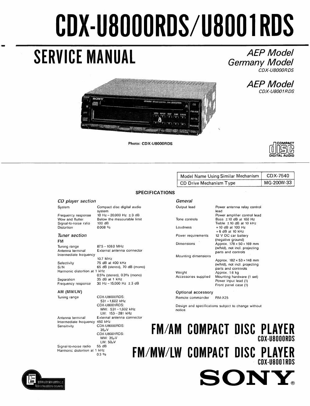
Sony cdx u 8001 rds service manual

This is the 59 pages manual for sony cdx u 8001 rds service manual.
Read or download the pdf for free. If you want to contribute, please mail your pdfs to info@audioservicemanuals.com.

Page: 1 / 59
left right
sony cdx u 8001 rds service manual

Extracted text from sony cdx u 8001 rds service manual (Ocr-read)


Page 2

CDX-U8000RDS/U8001RDS

TABLE OF CONTENTS

Section Title Page
Specifications ---------------------------------- 1
Servicing Note

1. Flexible Circuit Board Repairing ----------- 2

2. Removing the Flat Package [C --------------- z

3. Procedure of Replacing the Flexible

PC Film of the Display Board ------------- 3

SECTION 1. GENERAL

Features ..................................... 4

Precautions - ............


Location and Function of Controls ~~~~~~~ -

Detaching and Attaching the Front Panel ------- 7
Installation --------------------------------- 3
Connections ---------------------------------- 9

SECTION 2. IC PIN DESCRIPTION
2'1. Master Micrcomputer 10504
(uPD75518GF-029-3I39) """
22. Tuner Microcomputer IC67D (Tuner I.C707l]) ~ 17
2-3. Tuner Microcomputer 10601

(LLPD7SUGGFF18~3BE) """"""""""" 18
2-4. Tuner Microcomputer IC603 (LC7ZIGM) 21
2v5. Key Display Microcomputer ICBDZ

(uPD750086B-3B4) --------------------- 22

SECTION 3. MECHANICAL ADJUSTMENTS - - - 25

SECTION 4. ELECTRICAL ADJUSTMENTS ~~~~~ 25

SECTION 5. DIAGRAMS
5-1. Block Diaaxam .......................... 29
5-2. Printed Wiring Boards {MD Section) ----- 34
5-3. Schematic Diagram (MD Section) --------- 37
5-4. Semiconductor Lead Layouts ------------- 39
5-5. Printed Wiring Boards (Main Section) 40
5-6. Schematic Diagram (Main Section) ------ 43
5-7. Schematic Diagram (Display Section) 47
5-8. Printed Wiring Boards (Display Section) - 51
59. anefOI-ms .............................. 53
5-10. IC Block Diagram ------------------ 55

SECTION 6. EXPLODED VIEWS

1. General Section (I) ----------------------- 57
2. General Section (2) 5g
3. MD Section (1) -------- 59
4. MD Section (2) ........................... 50
5. MD Section (3) ............................ 61
SECTION 7. ELECTRICAL PARTS LIST -------- 62

SERVICING NOTE

1) Flexible Circuit Board Repairing

I Keep the temperature of the soldering iron around
270°C during repairing.

U Do not touch the soldering iron on the same con~
ductor of the circuit board (within 3 times).

0 Be careful not to apply force on the conductor
when soldering or unsoldering.

Notes on chip component replacement

0 Never reuse a disconnected chip component
0 Notice that the minus side oia tantalum capacitor
may be damaged by heat.

2) Removing the Flat Package IC

1. Prepare an enameled wire (0.3mm diameter) and
apply it to the back side of the IC pins as illus~
crated below.

Solder or fix with adhesive tape.

2. Heat the IC pin with the soldering iron and draw
the enameled wire so that the IC pin is removed
from the pattern as illustrated.

SAFETY-RELATED COMPONENT WARNING

COMPONENTS IDENTIFIED BY MARK A 0R DOTTED
LINE WITH MARK A ON THE SCHEMATIC DIAGRAMS
AND IN THE PARTS LIST ARE CRITICAL TO SAFE
OPERATION. REPLACE THESE COMPONENTS WITH
SONY PARTS WHOSE PART NUMBERS APPEAR AS
SHOWN IN THIS MANUAL OR IN SUPPLEMENTS PUB-
LISHED BY SONY.

_2_