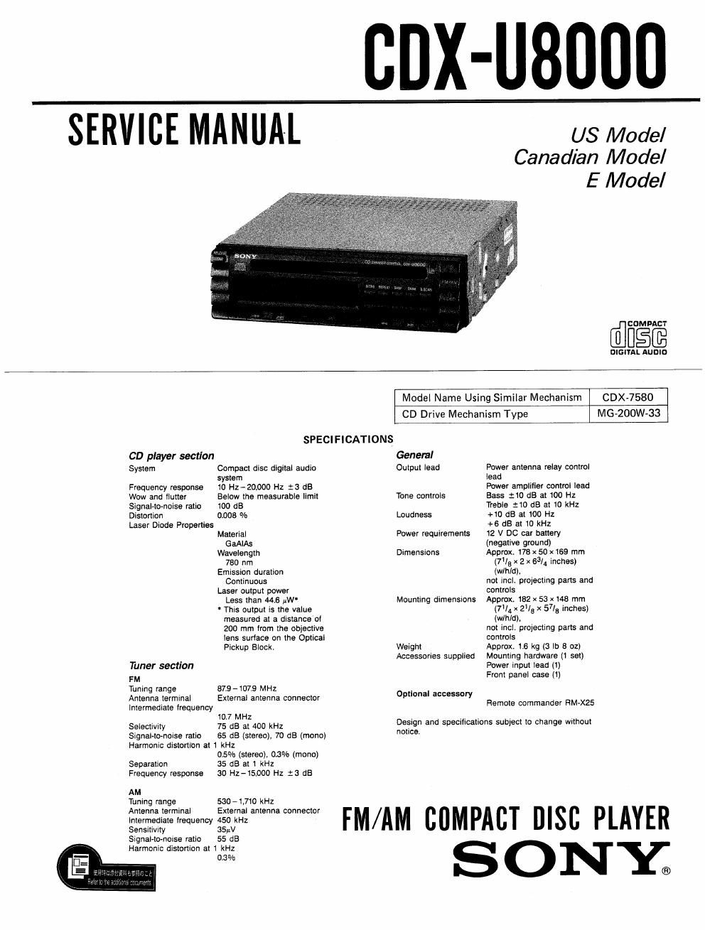
Sony cdx u 8000 service manual

This is the 59 pages manual for sony cdx u 8000 service manual.
Read or download the pdf for free. If you want to contribute, please mail your pdfs to info@audioservicemanuals.com.

Page: 1 / 59
left right
sony cdx u 8000 service manual

Extracted text from sony cdx u 8000 service manual (Ocr-read)


Page 1

CDX-UBUDO

SERVICE MANUAL

US Model
Canadian Model
E Model

COMPACT

DIGITAL AUDIO

CD player section
System

Frequency response
Wow and flutter
Signal-tonoise ratio
Distortion

Laser Diode Properties

Tuner section

FM

Tuning range

Antenna terminal
Intermediate frequency

Selectivrty
Signal-to-noise ratio

Model Name Using Similar Mechanism

CDX-7580

CD Drive Mechanism Type

MG-ZOOW-33

SPECIFICATIONS
General

Compact disc digital audio Output lead
system
10 Hz-ZOJJOO Hz 1'3 dB
Below the measurable limit Tone controls
100 £13
01306 % Loudness
Material Power requirements

GaAlAs
Wavelength Dimensions

780 nm
Emission duration

Continuous

Laser output power
Less than 44.6 uW

' This output is the value
measured at a distance'ol
200 mm from the objective
lens surtace on the Optical
Pickup Block.

87.9 -107.9 MHz
External antenna connector

10.7 MHZ
75 dB at 400 kHz
55 dB (stereo), 70 dB (mono)

Harmonic distortion at 1 kHz

Separation
Frequency response

AM

Tuning range

Antenna terminal
intermediate frequency
Sensitivity
Signal-tomoise ratio

0.5% (stereo). 0.3% (mono)
35 dB at 1 kHz
30 HZ-15,000 Hz :3 dB

530 - 1,710 kHz

External antenna connector
450 kHz

SSuV

55 dB

Harmonic distortion at 1 kHz

03 "/a

Mounting dimensions

Weight
Accessories supplied

Optional accessory

Power antenna relay control

lead

Power amplifier control lead

Bass :10 dB at 100 Hz

Treble :10 dB at 10 kHz

+10 dB at 100 Hz

+6 dB at 10 kHz

12 V DC car battery

(negative ground)

Approx. 176 x 50 x169 mm
(713 x 2 x 63/4 inches)
(wlhld).

not incL projecting pans and

controls

Approx 182 x 53 x 48 mm
(7V4 x 215 x 57/3 inches)
(WIN/d).

not incl. projecting parts and

controls

Approx 1.6 kg (3 lo 8 oz)

Mounting hardware (1 set)

Power input lead (1)

Front panel case (1)

Remote commander RM»X25

Design and specifications subject to change without

notice.

FM/AM COMPACT DISC PLAYER

ONY;

Page 2

CDX-USOOO

TABLE OF CONTENTS SERVICING NOTE


M Title PE 1) Flexible Circuit Board Repairing

Specifications .................................. 1 0 Keep the temperature of the soldering iron around

Servicing Note 270°C during repairing
1. Flexible Circuit Board Repairing ........... Z 0 Do not touch the soldering iron on the same com
2. Removing the Flat Package 10 ............... 2 ductor of the circuit board (within 3 times).
3. Procedure of Replacing the Flexible 0 Be careful not to apply force on the conductor

PC Film of the Display Board ............. 3 when soldering or unsoldering.

SECTION 1' GENERAL Notes on chip component replacement
Features ...................................... 4
precautions ....................... . 4 0 Never reuse a disconnected chip component.
Location and Function of Controls . . 5 0 Notice that the minus side ofa tantalum capacitor
Detaching and Attaching the Front Panel - 7 may be damaged by heat-
Installation .......................... . 3
Connections ................................... 9 2) Removing the Flat Package IC

1. Prepare an enameled wire (0.3mm diameter) and
apply it to the back side of the IC pins as illus-
trated below.

SECTION 2. IC PIN DESCRIPTION
2-1. Master Micrcomputer 10504
(uPD75518GF-029-3B9) ----------------- 11
2-2. Tuner Microcomputer IC601

(uPD7BIIBGF-F4U-SBE) ------------ .. 17
2-3. Tuner Microcomputer 10603 (L07216M) ----- 20 fi
24 Key Display Microcomputer ICEDZ /
(upmooacnrmmuil ---------------- 21

SECTION 3. MECHANICAL ADJUSTMENTS . - -- 23

SECTION 4. ELECTRICAL ADJUSTMENTS ----- 23 ,
Solder or fix With adhesive tape.

SECTION 5. DIAGRAMS

5.1, Block Diagram .......................... 27

5-2" PrmtedWiring Boards (MD Wm) 32 2. Heat the IC pin with the soldering iron and draw

53 Schematic Diagram (MD Section) """"" 35 the enameled wire so that the IC pin is removed

5-4. Semiconductor Lead Layouts ------------ 37 from the pattern as illustrated.

5-5. Printed Wiring Boards (Main Section) 38

5-6. Schematic Diagram (Main Section) ------- 41

5-7. Schematic Diagram (Display Section) 45
5-8. Printed Wiring Boards (Display Section) - 49

5-9. Waveforms ............................. 51
5-10 {(3 Block Diagram ....................... 53
SECTION 6. EXPLODED VIEWS
1. General Section (1) ----------------------- 55
2. General Section (2) ----------------------- 55
3_ MD Section (1) ............................ 57
4, MD Section (2) ............................ 58
5. MD Section (3) ............................ 59
SECTION 7. ELECTRICAL PARTS LIST -------- so

ATTENTION AU COMPOSANT AYANT RAPPORT

SA FETY-RELATED COMPONENT WARNING II

COMPONENTS IDENTIFIED BY MARK A OR DOTTED
LINE WITH MARK A ON THE SCHEMATIC DIAGRAMS
AND IN THE PARTS LIST ARE CRITICAL TO SAFE
OPERATION. REPLACE THESE COMPONENTS WITH
SONY PARTS WHOSE PART NUMBERS APPEAR AS
SHOWN IN THIS MANUAL OR IN SUPPLEMENTS PUB-
LISHED RV SONV.

A LA sEcumréI

LES COMPOSANTS IDENTIFIES PAR UNE MAROUE A
sun LES DIAGRAMMES scHéMAnouES ET LA LISTE
DES PIECES sour crIITIOUEs POUR LA sécURIré
DE FONCTIONNEMENT. NE REMPLACER CEs com
POSANTS oue PAR oes PIECES sONV pour LES
NUMéRos sour DONNés DANS CE MANUEL ou
oANs LES SUPPLEMENTS Pueués PAR souv.