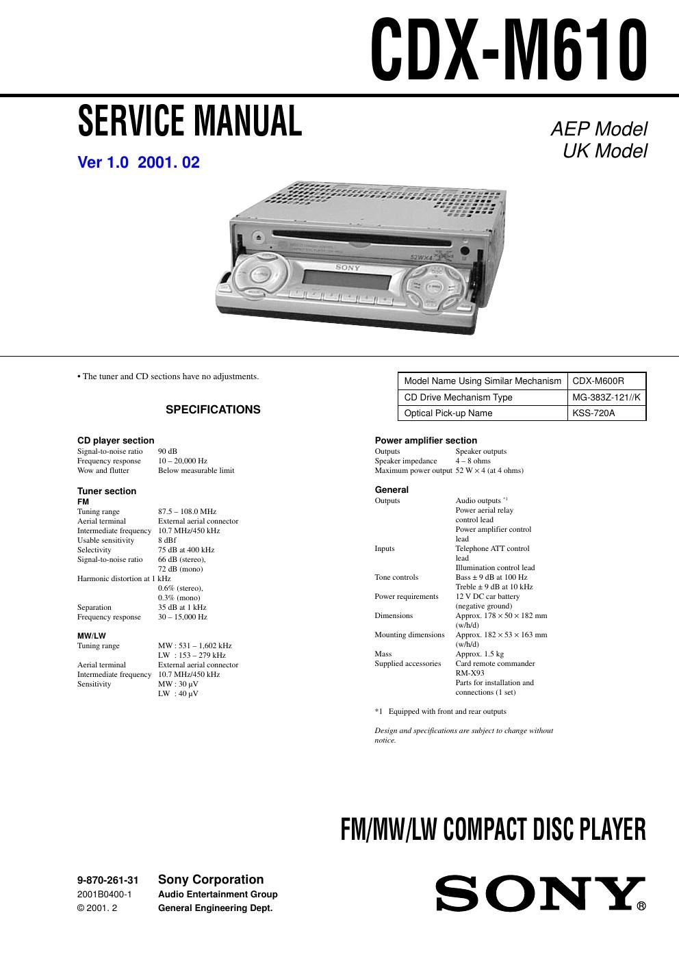
Sony cdx m 610 service manual

This is the 70 pages manual for sony cdx m 610 service manual.
Read or download the pdf for free. If you want to contribute, please mail your pdfs to info@audioservicemanuals.com.

Page: 1 / 70
left right
sony cdx m 610 service manual

Extracted text from sony cdx m 610 service manual (Ocr-read)


Page 1

2 stand SAFETY-RELATED COMPONENT WARNING!! COMPONENTS IDENTIFIED BY MARK 0 OR DOTTED LINE WITH MARK 0 ON THE SCHEMATIC DIAGRAMS AND IN THE PARTS LIST ARE CRITICAL TO SAFE OPERATION. REPLACE THESE COMPONENTS WITH SONY PARTS WHOSE PART NUMBERS APPEAR AS SHOWN IN THIS MANUAL OR IN SUPPLEMENTS PUBLISHED BY SONY. SERVICE NOTES CDX-M610 Notes on Chip Component Replacement -Never reuse a disconnected chip component. -Notice that the minus side of a tantalum capacitor may be dam- aged by heat. NOTES ON HANDLING THE OPTICAL PICK-UP BLOCK OR BASE UNIT The laser diode in the optical pick-up block may suffer electrostatic breakdown because of the potential difference generated by the charged electrostatic load, etc. on clothing and the human body. During repair, pay attention to electrostatic breakdown and also use the procedure in the printed matter which is included in the repair parts. The flexible board is easily damaged and should be handled with care. NOTES ON LASER DIODE EMISSION CHECK The laser beam on this model is concentrated so as to be focused on the disc reflective surface by the objective lens in the optical pick- up block. Therefore, when checking the laser diode emission, ob- serve from more than 30 cm away from the objective lens.NOTE FOR THE OPENING OF THE FRONT PANEL In this set, the front panel is lowered to below the bottom face when it is opened. When servicing the set, place it on a stand having a height of about 2 cm. This label is located on the bottom of the chassis. This label is located on the drive units internal chassis. CLASS PRODUCT LASER 1 CAUTION INVISIBLE DO NOT STARE INTO BEAM OR VIEW DIRECTLY WITH OPTICAL INSTRUMENTSLASER RADIATION When replacing the chassis (T) of mechanism deck which have the CAUTION LABEL attached, please be sure to put a new CAUTION LABEL (3-223-913-11) to the chassis (T).

Page 2

3 MODEL IDENTIFICATION There are two types of main board in according destination. -“ MAIN board (side A) -“ magnify magnifymagnify TYPE A TYPE B R818 R854 R849 R853Indicated language English, TYPE A aa Ă—Ă—Spanish, Portuguese, Swedish French, TYPE BĂ—Ă— aa German, Italian, Dutch TYPE A or B model can also be identified from the front panel display language. For a switching method of display language, see page 11.