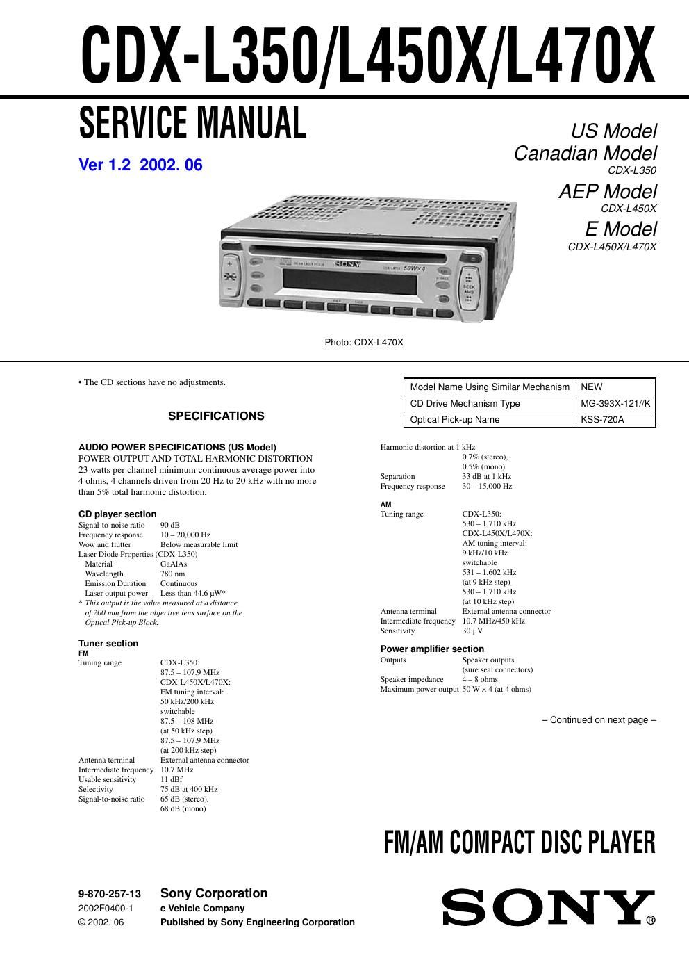
Sony cdx l 450 x service manual

This is the 72 pages manual for sony cdx l 450 x service manual.
Read or download the pdf for free. If you want to contribute, please mail your pdfs to info@audioservicemanuals.com.

Page: 1 / 72
left right
sony cdx l 450 x service manual

Extracted text from sony cdx l 450 x service manual (Ocr-read)


Page 2

CDX- L350/L450X/L470X

General
Outputs Audto output
Power amplifier control
lead (CDXVLJSO)
Power antenna relay
control lead (CDXVLSSO)
Power aerial relay control
lead (CDX7L450X/L47OX)
Bass :10 dB at 20 1-12 (CDXVLSSO)
Treble :10 dB at 20 kHz (CDXVLSSO)
Bass :9 dB at 100 1-12 (L450X/L470X)
Treble :9 dB at 10 kHz (L450X/L470X)
12 v DC car battery
(negative ground)
Approx. 178 X 50 X 176 mm
(71/8 X 2 X 7m.)
(w/h/d)
Mounting dimensions Approx. 182 X 53 X 161 mm
(71/4 >< 21/3 X 6 Win.)
(w/h/d)
Mass Approx. 1.2 kg (2 1b. 1002,)
Supplied accessories Parts for installation and
connections (1 set)
Front panel case (1)
Card remote commander
Rer1 15 (CDX7L350/L470X)

Tone controls

Power requirements

Dimensrons

Note (L450X/L470X)
This unit cannot be connected to a digital
preamplifier or an equalizer.

Dmgn rind tchi/it'rllmnx um sub/cc! m change Wit/11ml
llltllL'B.

SERVICE NOTES

NOTES ON HANDLING THE OPTICAL PICK-UP BLOCK
OR BASE UNIT

The laser diode in the optical pickeup block may suffer electrostatic
breakdown because of the potential difference generated by the
charged electrostatic load, etc. on clothing and the human body.
During repair, pay attention to electrostatic breakdown and also use
the procedure in the primed matter which is included in the repair
parts.

The flexible board is easily damaged and should be handled with
care.

NOTES ON LASER DIODE EMISSION CHECK

The laser beam on this model is concentrated so as to be focused on
the disc reflective surface by the objective lens in the optical pick,
up block. Therefore, when checking the laser diode emission, ob,
serve from more than 30 cm away from the objective lens.

Notes on Chip Component Replacement

0 Never reuse a disconnected chip component.

I Notice that the minus side of a tantalum capacitor may be dame
aged by heat.

SAFETY-RELATED COMPONENT WARNING !!

COMPONENTS IDENTIFIED BY MARK A OR DOTTED LINE
WITH MARK A ON THE SCHEMATIC DIAGRAMS AND IN
THE PARTS LIST ARE CRITICAL TO SAFE OPERATION.
REPLACE THESE COMPONENTS WITH SONY PARTS WHOSE
PART NUMBERS APPEAR AS SHOWN IN THIS MANUAL OR
IN SUPPLEMENTS PUBLISHED BY SONY.

2

US/Canadian/E model:

CAUTION

Use of controls or adjustments or performance of procedures
other than those specified herein may result in hazardous
radiation exposure.

If the optical pickeup block is defective, please replace the whole
optical pick-up block.

Never turn the semieflxed resistor located at the side of optical
pickeup block.

optical pick-up block

semi-fixed resistor

AEP model:

CLASS 1

LASER PRODUCT

This product is classified as a CLASS I LASER PRODUCT.
This label is located on the bottom of the
cha s.

CAUTION-INVISIBLE LASER RADIATION WHEN OPEN
DO NOT STARE INTO BEAM 0R
VIEW DIRECTLY WITH OPTICAL INSTRUMENTS

Thi\ abel is located on the drive unit's intemal
cha. s.

When replacing the chassis (T) of mechanism deck which have
the CAUTION LABEL" attached, please be sure to put a new
CAUTION LABEL (Ii-22331341) to the chassis (T).

ATTENTION AU COMPOSANT AYANT RAPPORT
A LA SECURITEH

LES COMPOSANTS IDENTIFIES PAR UNE MARQUE A SUR LES
DIAGRAMMES SCHEMATIOUES ET LA LISTE DES PIECES
SONT CRITIQUES POUR LA SECURITE DE FONCTIONNEMENT.
NE REMPLACER CES COMPOSANTS QUE PAR DES PIECES
SONY DONT LES NUMEROS SONT DONNES DANS CE MANUEL
OU DANS LES SUPPLEMENTS PUBLIES PAR SONY.