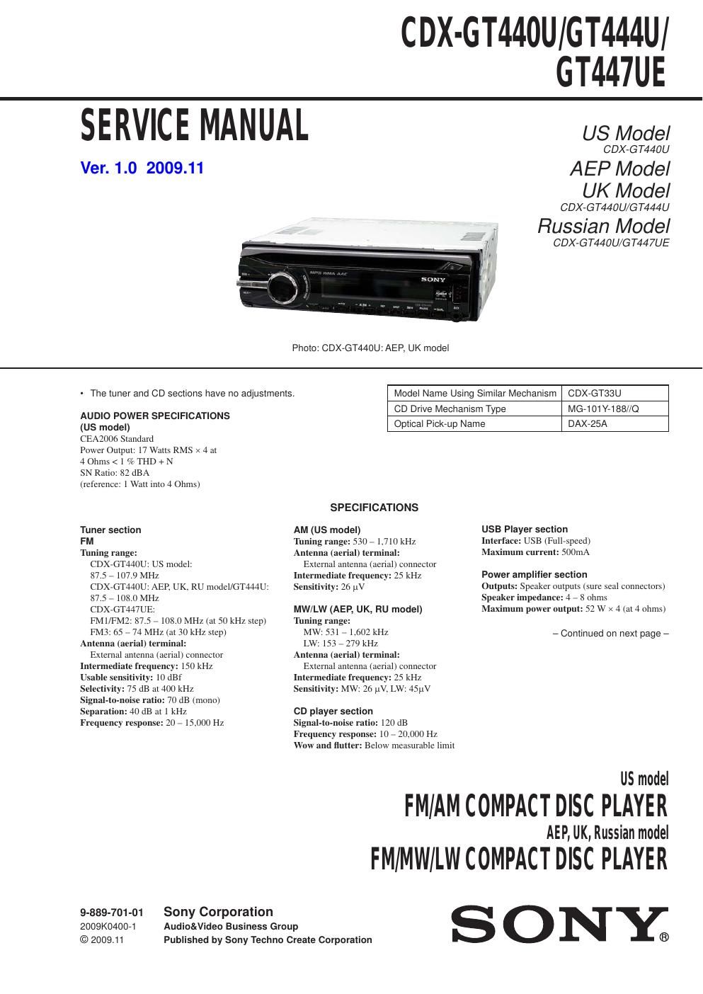
Sony cdx gt 440u gt444u gt447ue service manual

This is the 40 pages manual for sony cdx gt 440u gt444u gt447ue service manual.
Read or download the pdf for free. If you want to contribute, please mail your pdfs to info@audioservicemanuals.com.

Page: 1 / 40
left right
sony cdx gt 440u gt444u gt447ue service manual

Extracted text from sony cdx gt 440u gt444u gt447ue service manual (Ocr-read)


Page 2

CDX-GT440U/GT444U/GT447U E

General
Outputs:
Audio outputs terminal
(front (US model), sub/rear switchable)
Power antenna (aerial) relay control terminal
Power amplifier control terminal
Inputs:
Telephone ATT control terminal (AER UK, RU model)
Remote controller input terminal
Antenna (aerial) input terminal
AUX inputjack (stereo minijack)
USB signal input terminal
Tone controls:
Low: :10 dB at 60 Hz (XPLOD)
Mid: :10 dB at 1 kHz (XPLOD)
High: :10 dB at 10 kHz (XPLOD)
Power requirements: 12 V DC car battery
(negative ground (earth))
Dimensions: Approx. 178 x 50 x 179 mm
(7 Us x 2 X 7 1/x in.) (w/h/d)
Mounting dimensions:
Approx. 182 X 53 X 162 mm
(71/4 >< 21/8 x 6 1/2 in.) (w/h/d)
Mass: Approx. 1.2 kg (2 lb. 11 oz.)
Supplied accessories:
Card remote commander: RM-XlSl (US model)
Parts for installation and connections (1 set)

Design and specifications are subject to change
without notice.

- Abbreviation
RU :Ftussian model

SAFETY-RELATED COMPONENT WARNING!

COMPONENTS IDENTIFIED BY MARK A OR DOTTED LINE
WITH MARK A ON THE SCHEMATIC DIAGRAMS AND IN
THE PARTS LIST ARE CRITICAL TO SAFE OPERATION.
REPLACE THESE COMPONENTS WITH SONY PARTS
WHOSE PART NUMBERS APPEAR AS SHOWN IN THIS
MANUAL OR IN SUPPLEMENTS PUBLISHED BY SONY.

2

NOTES ON HANDLING THE OPTICAL PICK-UP
BLOCK OR BASE UNIT

The laser diode in the optical pickAup block may suffer electroA
static breakadown because of the potential difference generated by
the charged electrostatic load, etc. on clothing and the human body.
During repair, pay attention to electrostatic break~down and also
use the procedure in the printed matter which is included in the
repair parts.

The flexible board is easily damaged and should be handled with
care.

NOTES ON LASER DIODE EMISSION CHECK

The laser beam on this model is concentrated so as to be focused
on the disc reflective surface by the objective lens in the optical
pickup block. Therefore, when checking the laser diode emission,
observe from more than 30 cm away from the objective lens.

NOTES ON CHIP COMPONENT REPLACEMENT

' Never reuse a disconnected chip componentt

- Notice that the minus side of a tantalum capacitor may be
damaged by heat.

TEST DISCS
Please use the following test discs for the check on the CD
section.

YDES-18(Pait No. 3702A101-Ol)
PATD~012 (Part No. 4225-20301)

CAUTION

Use of controls or adjustments or perlormance of procedures
other than those specified herein may result in hazardous radia-
tion exposure.

If the optical pick-up block is defective, please replace the whole
optical pick-up block.

Never tum the semifixed resistor located at the side of optical
pick-up block.

optical pick-up

semi-fixed resistor