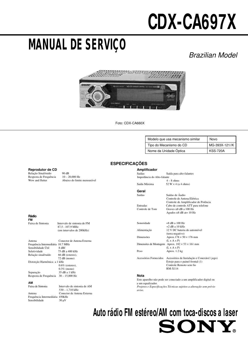
Sony cdx ca 697x

This is the 21 pages manual for sony cdx ca 697x.
Read or download the pdf for free. If you want to contribute, please mail your pdfs to info@audioservicemanuals.com.

Page: 1 / 21
left right
sony cdx ca 697x

Extracted text from sony cdx ca 697x (Ocr-read)


Page 2

3-1. DESCRIQAO DOS PINOS DOS IC's

~ CDX-CA697X
SEQAO 3
DIAGRAMAS

- IC801 MN101C49KTG1 (SYSTEM CONTROL)

Pin No. Pin Name I/O Pin Description
1 VREFi 7 Ground for A/D converter power supply
2 VSM I S»meter voltage detection signal input from tuner unit (TU601)
3 NIL I Connect to ground.
4 KEYINI I Key signal input
5 KEYINO I Key signal input
6 RC 1N0 I Rotary commander key signal input from remote injack (CNPSOI)
7, 8 NIL I Not used. (Connect to ground.)
Destination set up detection signal input (L: CDX-CA650X/CA660X,
9 DSTSEL I
H: CDX-CA690X)
10 VREF+ i A/D converter power supply
11 VDD 7 Power supply (+5 V) input pin
12 OSCOUT 0 High speed clock signal output (18.432 MHZ)
13 OSCIN I High speed clock signal input (18.432 MHZ)
14 V55 7 Ground for power supply
15 XIN 1 Low speed clock signal input (32.768 kHz)
16 XOUT 0 Low speed clock signal output (32.768 kHz)
17 MMOD I Memory mode select signal input (Input to Low (single chip mode).)
(Connect to ground.)
18 LCDSO 0 LCD serial data signal output to LCD driver (ICSOI)
19 LCDCE 0 LCD chip enable signal output to LCD driver (IC501)
20 LCDCKO O LDC serial clock signal output to LCD driver (IC501)
21 CD SO/TSO 0 CD servo IC serial data signal output
22 CD SI/TSI I CD servo IC serial data signal input
23 CD CKO/TCKO 0 CD servo IC serial clock signal output
24 W 0 System reset signal output to bus interface (IC803)
25 m 0 Bus on signal output to bus interface (IC803)
26 KEYACK I Key acknowledge detection signal input
27 NIL I Not used. (Connect to ground.)
28 m I Back up current detection signal input
29 SIRCS I Remote signal input from remote control receiver (IC502)
30 CD SELFSW I CD mechanism self load position detection switch signal input from self switch (SW2)
31 CD PACK 1 CD text pack sync signal input from CD servo (1C1)
32 NIH 1 Connect to power supply.
33 W I microcomputer reset signal input from reset IC (1C802) L": reset
34 m I Front panel attachment detection signal input from nose detect switch (8902) L: ON
35 BEEP O Beep signal output to power amp (IC404)
36 NCO 0 Not used. (Open)
37 m I Test mode detection signal input
38 m I Accessory power supply detection signal input
39 NCO 0 Not used. (Open)
40 TELATT 1 Telephone ATT detection signal input
41 NIH 1 Connect to power supply.
42 BUSSO O SonyeBus serial data signal output to bus interface (IC803)
43 BUSSI I SonyABus serial data signal input from bus interface (IC803)
44 BUSCKO O SonyABus serial clock signal output to bus interface (IC803)
45 IZCSIO I/O I2C bus serial data signal input/output
46 NCO 0 Not used. (Open)
47 I2CCKO 0 12C bus serial clock signal output
48 NCO 0 Not used. (Open)
49 TUNON 0 Tuner power supply control signal output to power supply (1C901)
50 PW ON 0 System power supply control signal output to power supply (IC901)

13