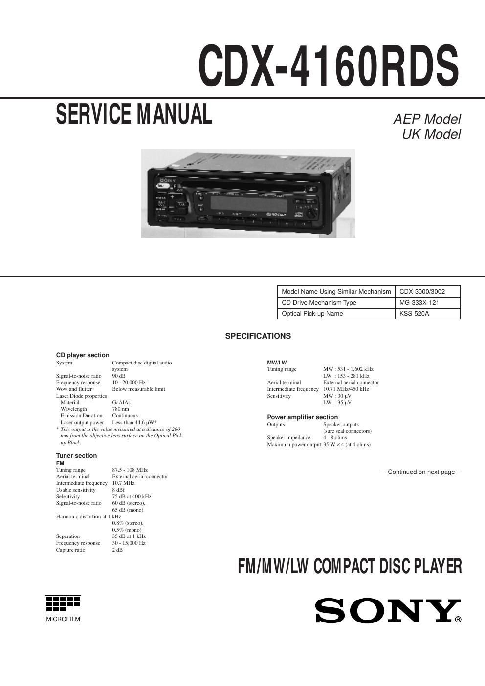
Sony cdx 4160 rds service manual

This is the 44 pages manual for sony cdx 4160 rds service manual.
Read or download the pdf for free. If you want to contribute, please mail your pdfs to info@audioservicemanuals.com.

Page: 1 / 44
left right
sony cdx 4160 rds service manual

Extracted text from sony cdx 4160 rds service manual (Ocr-read)


Page 2

Ð 3 Ð TABLE OF CONTENTS 1. GENERAL Location of Controls .................................................................. 4 Setting the Clock ....................................................................... 4 CD Player .................................................................................. 4 Radio ......................................................................................... 5 RDS ........................................................................................... 6 Other Functions ......................................................................... 7 Additional Information .............................................................. 8 Connections ............................................................................... 9 2. DISASSEMBLY 2-1. Cover Assy .......................................................................... 11 2-2. Front Panel Assy ................................................................. 11 2-3. Sub Panel ............................................................................. 12 2-4. CD Mechanism Block ......................................................... 12 2-5. Main Board .......................................................................... 13 2-6. Heat Sink ............................................................................. 13 2-7. Chassis (T) Sub Assy .......................................................... 14 2-8. Lever Assy ........................................................................... 14 2-9. Servo Board ......................................................................... 15 2-10. Roller Assy .......................................................................... 15 2-11. Chassis (OP) (O/S) Assy ..................................................... 16 2-12. Optical Pick-up Block ......................................................... 16 3. ELECTRICAL ADJUSTMENTS Tuner Section ........................................................................... 17 CD Section .............................................................................. 20 4. DIAGRAMS 4-1. IC Pin Description ............................................................... 21 4-2. Block Diagram .................................................................... 23 4-3. Circuit Boards Location ...................................................... 25 4-4. Printed Wiring Boards ÐCD Mechanism SectionÐ .............. 26 4-5. Schematic Diagram ÐCD Mechanism SectionÐ .................. 29 4-6. Printed Wiring Boards ÐMain SectionÐ .............................. 33 4-7. Schematic Diagram ÐMain SectionÐ ................................... 35 4-8. Printed Wiring Board ÐDisplay SectionÐ ............................ 40 4-9. Schematic Diagram ÐDisplay SectionÐ ............................... 42 5. EXPLODED VIEWS 5-1. Chassis Section .................................................................... 51 5-2. Front Panel Section ............................................................. 52 5-3. CD Mechanism Section (1) ................................................. 53 5-4. CD Mechanism Section (2) ................................................. 54 5-5. CD Mechanism Section (3) ................................................. 55 6. ELECTRICAL PARTS LIST...................................... 56