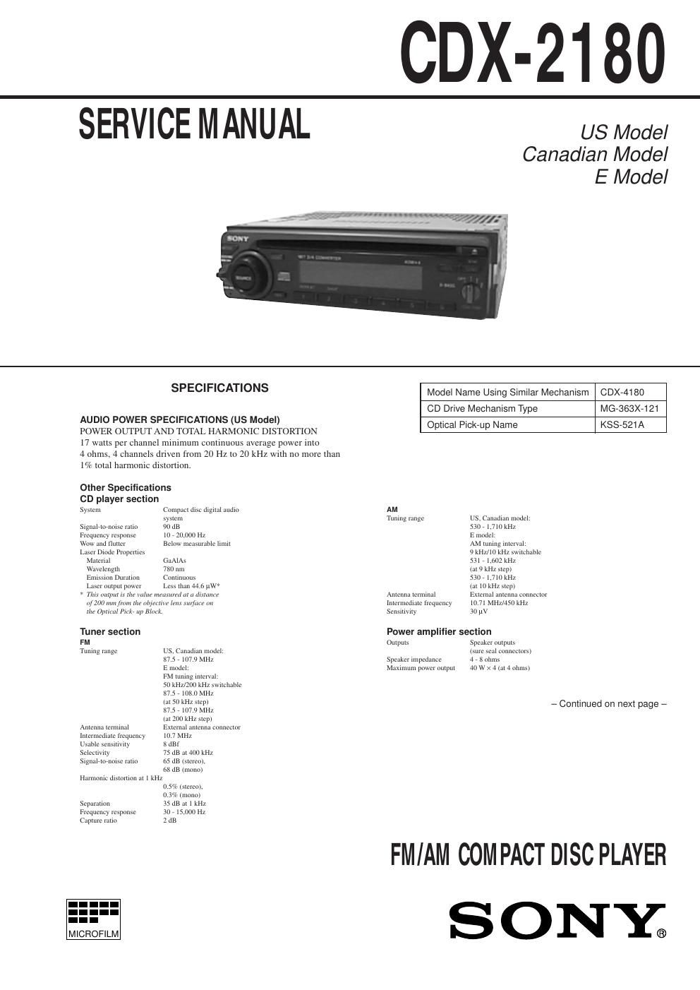
Sony cdx 2180

This is the 10 pages manual for sony cdx 2180.
Read or download the pdf for free. If you want to contribute, please mail your pdfs to info@audioservicemanuals.com.

Page: 1 / 10
left right
sony cdx 2180

Extracted text from sony cdx 2180 (Ocr-read)


Page 1

Ð 19 Ð 4-1. IC PIN DESCRIPTION ¥ IC801 mPD17705GC-526-3B9 (SYSTEM CONTROL) Pin No. Pin Name I/O Pin Description 1 SIRCS I SIRCS input (A/D) 2 IN-SW I CD mechanism position detection 3 D-SW I CD mechanism position detection 4 SELF-SW I CD mechanism position detection 5 L-SW I LIMIT switch 6 LM-EJ O Loading motor control (Eject direction) 7 LM-LOD O Loading motor control (Loading direction) 8 ANT-ON O Power control for amplifier. 9 MONO O Force MONO output 10 SD I SD signal input 11 BAND-SW I Band plan setting of general area. 12 AREA1-SW I Destination select 1 13 AREA2-SW I Destination select 2 14, 15 RE1, 2 I Rotary encoder input 1, 2 16 SEEK/SEEK O SEEK output 17 Ð 20 NC Ñ Not used. 21 GND3 Ñ GND 22 Ð 24 KEYIN3 Ð 1 I A/D key input 3 Ð 1 25 ROT-IN I Rotary commander input 26 S-METER I FM and AM common signal meter A/D conversion input 27 TEST-SW I TEST mode select input 28 AM-IFC I AM center frequency input 29 FM-IFC I FM center frequency input 30 VDD2 Ñ Power supply (+5 V) 31 VCOH-FM I Local oscillation frequency input (FM) 32 VCOL-AM I Local oscillation frequency input (AM) 33 GND2 Ñ GND 34 NC Ñ Not used. 35 EO1-PDOUT O Error out output 36 TESTO Ñ Fixed at ÒLÓ. 37 AM-ON(TU-ON) O AM power output (AM select) 38 FM-ON(FM/AM) O FM power output (FM select) 39 LCL/DX O LOCAL/DX select (ÒHÓ : LOCAL, ÒLÓ : DX) 40 BEEP O BEEP output 41 ACC-IN I Accessory input 42 SCOR I SUBQ data read request 43 MUTE O System mute output 44 AMP-MUTE O Power amplifier mute output 45 TEL-MUTE O Telephone mute output 46 PH2 Ñ Fixed at ÒHÓ in this set. 47 VOL-CE O Electric volume chip select 48 VOL-CLK O Electric volume serial clock 49 VOL-DATA O Electric volume serial data 50 EMPHO O De-emphasis control output 51 PW-ON O System power control 52 MD-ON O Loading motor power 53 CD-ON O Servo drive power 54 ILL-ON O Illumination output 55, 56 MOD1, 2 O Bus boost control 1, 2 57 PH3 Ñ Fixed at ÒHÓ in this set. 58 LCD-CE O LCD drive chip select output SECTION 4 DIAGRAMS