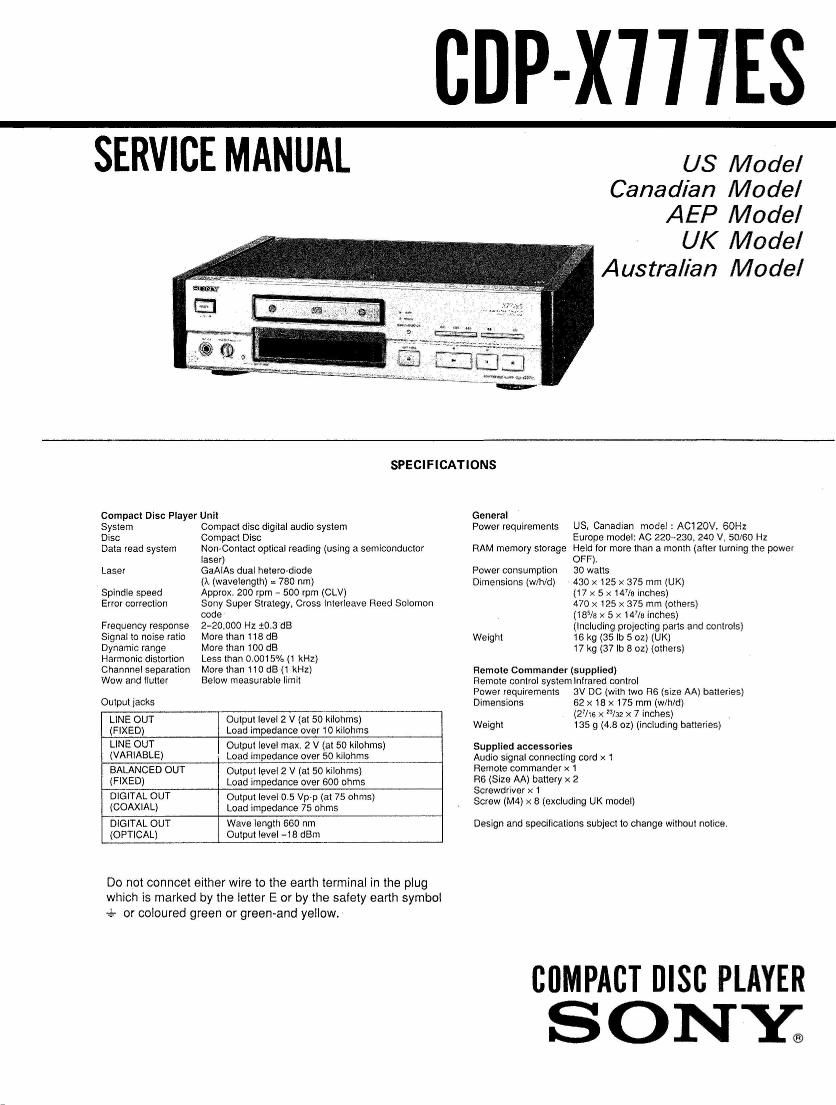
Sony CDP X777 ES Service Manual

This is the 41 pages manual for Sony CDP X777 ES Service Manual.
Read or download the pdf for free. If you want to contribute, please mail your pdfs to info@audioservicemanuals.com.

Page: 1 / 41
left right
Sony CDP X777 ES Service Manual

Extracted text from Sony CDP X777 ES Service Manual (Ocr-read)


Page 1

CDP-X'ITIES

SERVICE MANUAL

US Model
Canadian Model
AEP Model

UK Model
Australian Model

SPECIFICATIONS

Compact Disc Player Unit

System Compact disc digital audio system

Disc Compact Disc

Data read system Non-Contact optical reading (using a semiconductor
laser)

Laser GaAlAs dual hetero-diode

(it (wavelength) = 780 rim)

Approx. 200 rpm - 500 rpm (CLV)

Sony Super Strategy, Cross interleave Reed Solomon
code

Frequency response 240,000 Hz :0.3 dB

Signal to noise ratio More than t18 dB

Dynamic range More than 100 dB

Harmonic distortion Less than 0.0015% (1 kHz)

Channnel separation More than 110 dB (1 kHz)

Wow and llutter Below measurable limit

Spindle speed
Error correction

Output jacks
LINE OUT Output level 2 V (at 50 kilohms)
(FIXED) Load impedance over 10 kilohms
LINE OUT Output level max. 2 V (at 50 kilohms)
(VARIABLE) Load impedance over 50 kilohms
BALANCED OUT Output level 2 V (at 50 kilohms)
(FIXED) Load impedance over 600 ohms
DIGITAL OUT Output level 0.5 Vpp (at 75 ohms)
(COAXIAL) Load impedance 75 ohms
DIGITAL OUT Wave length 560 nm
(OPTICAL) Output level ~18 dBm

Do not conncet either wire to the earth terminal in the plug
which is marked by the letter E or by the safety earth symbol
e- or coloured green or green-and yellow.

General
Power requirements US, Canadian model .' AC120V, 60H:
Europe model: AC 2204230. 240 V, 50/60 Hz
RAM memory storage Held for more than a month (after lurning the power
OFF),
30 walls
430 x125 X 375 mm (UK)
(17 x 5 x 14% inches)
470 x 125 x 375 mm (others)
(185/3 x 5 x 14% inches)
(Including prmecling parts and controls)
Weight 16 kg (35 lb 5 oz) (UK)
17 kg (37 lb 8 02) (others)

Power consumption
Dimensions (w/h/d)

Remote Commander (supplied)
Remote control system Infrared control
Power requirements 3V DC (with two H6 (size AA) batteries)
Dimensions 62 x 18 x 175 mm (w/h/d)

(The x 23/32 x 7 inches) ,
Weight 135 g (4.8 oz) (including batteries)

Supplied accessories

Audio signal connecting cord x 1
Remote commander x 1

R6 (SIZE AA) battery x 2

Screwdriver x 1

Screw (M4) x B (excluding UK model)

Design and specifications subject to change without notice.

chPAcr nrsc PLAYER
S ONY;

Page 2

CDP-X777ES I

TABLE OF CONTENTS

Section Title Page
Specifications ....... . ............................................... u ............ 1
Before Use (Transportion Screw) ~~~~~~~~~~~~~~~~~ ~~~~~~~~~~~~~~~~~ 2
1. SERVICING 01-5.. .................................................... 3
2. GENERAL
21. Location and Function of Controls 6
22, Playing a Disc ........................... 7
2-3. Adjusting the Volume ~~~~~ 7
24. Time Display During Play 7


Section Title

4, DIAGRAMS

4~1. Circuit Boards Location~
4~2, Block Diagram.

4-3. Printed Wiring Boards (Digital Section)
44. Schematic Diagrams (Digital Section).
4-5i Schematic Diagrams (Audio Section)"
46. Printed Wiring Boards (Audio Section)
- 10 Block Diagrams ~~~~~~~~~~~~~~~~
0 Semiconductor Lead Layouts ~~~~~


2.5. Information Display ............................................. 3 5. EXPLODED VIEws..............i, ............................ . ..... 37
2-6. Location and Function of Controls
(The Remote Commander) 6. ELECTRICAL PARTS LIST ~~~~~~~~~~~~~~~~~~~~~~~~~~~~~ . ~~~~~ ~44
2-7. Connections~~
3. ELECTRICAL ADJUSTMENTS
Before Use nsportatl Screw

Before starting any operation, be sure to release the
transportation screw (for protection of the laser
pickup and internal mechanism) located on the
bottom of the unit. Turn this screw in the direction of
the arrow, following the Caution Sheet attached to
the bottom plate. To release the transportation screw,
open the cap and turn the screw counterclockwise 180
degrees using the provided screwdriver. Be careful
not to turn screw too far, as it could damage the
internal mechanism or cause a malfunction.

Before transporting this unit, tighten the screw firmly.

SAFETY-RELATED COMPONENT WARNING

COMPONENTS IDENTIFIED BV MARK A OR DOTTED
LINE WITH MARK A ON THE SCHEMATIC DIAGRAMS
AND IN THE PARTS LIST ARE CRITICAL TO SAFE
OPERATION. REPLACE THESE COMPONENTS WITH
SONY PARTS WHOSE PART NUMBERS APPEAR AS
SHOWN IN THIS MANUAL OR IN SUPPLEMENTS PUB-
LISHED BY SONY,

When rotating the
screw, be sure to place
the unit upside down

Caution Sheet
(on the bottom plate)

ATTENTION AU COMPQSANT AYANT RAPPORT
A LA SECURITEI

LES COMPOSANTS IDENTIFIES PAR UNE MARQUE A
sun LES DIAGRAMMES SCHEMATlOUES ET LA LISTE
DES PIECES SONT camouss POUR LA sécumré
DE FONCTIONNEMENT. NE REMPLACER css COMA
POSANTS QUE PAR DES PIECES souv DONT LES
NUMEROS sour DONNES DANS CE MANUEL ou
DANS LES SUPPLEMENTS PUBLIES PAR 50m.

*2-