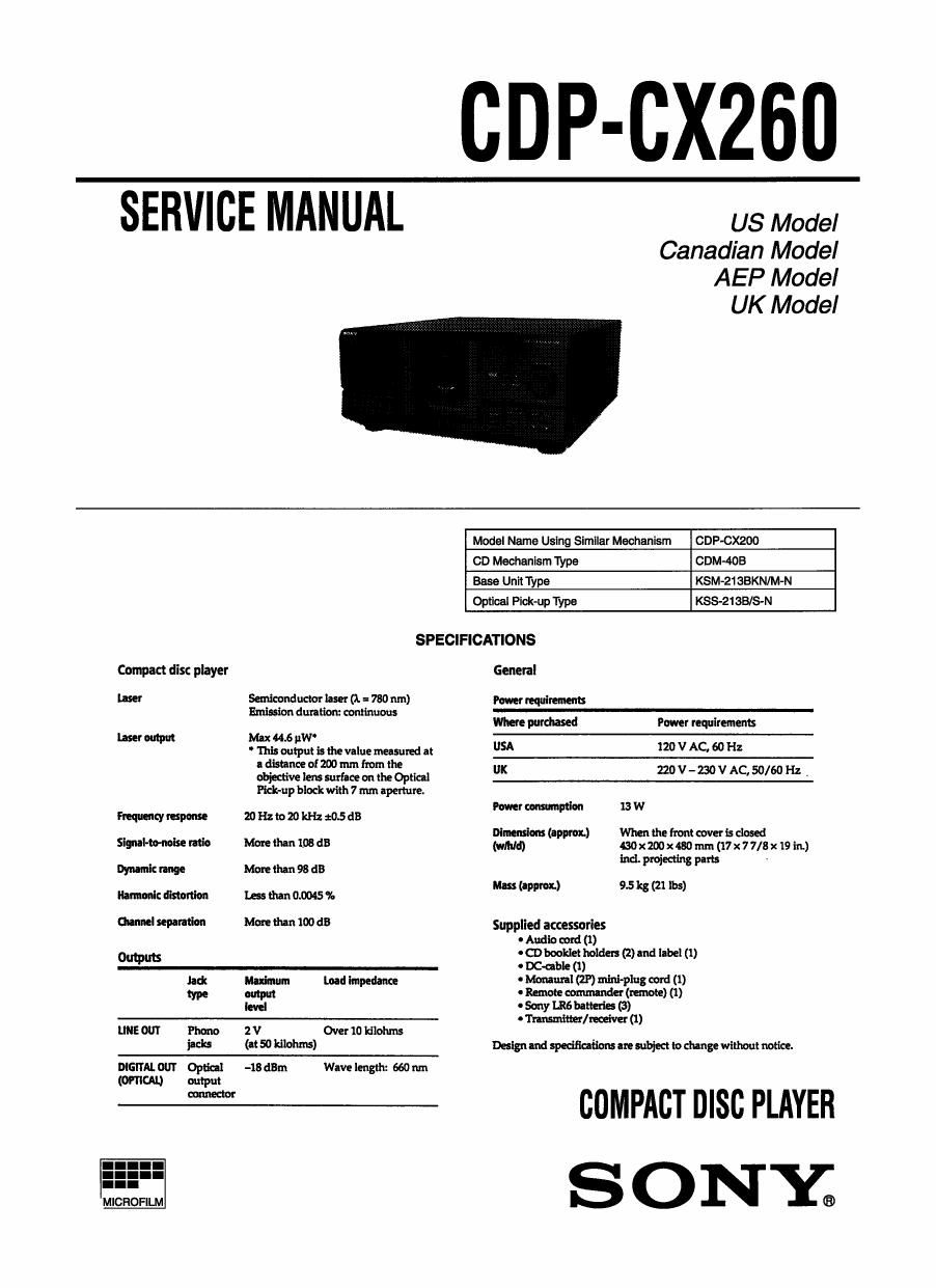
Sony CDP CX260 Service Manual

This is the 51 pages manual for Sony CDP CX260 Service Manual.
Read or download the pdf for free. If you want to contribute, please mail your pdfs to info@audioservicemanuals.com.

Page: 1 / 51
left right
Sony CDP CX260 Service Manual

Extracted text from Sony CDP CX260 Service Manual (Ocr-read)


Page 1

CDP-CXZBU

SERVICE MANUAL us Model

Canadian Model
AEP Model
UK Model

Model Name Using Simllar Mechanism CDP-CXZOO
CD Mechanism Type COM-408
Base Unit Type KSM-2138KN/M-N
Optical Pick-up Type KSS-21SB/S«N
SPECIFICATIONS
Compact disc player General
laser Senflconducmr laser (1. a 780 nm) Power requirements
mission duralion: continuous
Where purchased Power requlremenrs
mar mtwt Max 44.6 uW
' This output is the value measured at USA 120 V AC, 60 Hz
a distance of 200 mm from the
objective lens surface on the Optical UK 220 V _ 230 V AC 50/60 Hz -
Pick-up block with 7 mm aperture.
Power mmptlan 13 W

Premenzyrespome zoflzcuzokfluosds
Dimensions (approx) Mien the from cover is closed

Signal-mick: mic Manchu 1.08 dB (wmid) BOXZMXASOmrn (17x77/8x 19 in)
Ind. projecting park
Dyrumk range More than 98 dB
Mas I 9.5 21 lb
Harmonic distmion less than 0.0)45 36 ( pm) k 5)
Channel sepamlon More than 100 dB Supplied accessories
' Audio cord (1)
Input 0 CD booklet holder! (2) and label (I)
O 0 DCchble (1)
3: w. load Impedance Mammal (2P) maul-12mg cor)dé1))
m . Remote commander m
Mel O Sony IRE bulletin (3)
- Transmittal receiver (1)
LINE OUT Phone 2 V Over 10 kilohms
jack: (er 50 ldlohrm) Designand specificaiim are subject to change without notice.
DIGITAL OUT Optical -18 dBm Wave length: 660 run
(omuu output

W COMPACT DISC PLAYER
S 0 NY;

Page 2

Laser component in this product is capable of emitting radiation
exceeding the limit for Class 1.

This appliance is classified as
a CLASS 1 LASER product.
$355.1. $2.333 The CLASS 1 LASER PROD-
KLAss 1 LASERAPPARAT UCI MARKING is located on
the rear exterior.

The following
caution label is
located inside of
the unit

CAUTION : INVISIBLE usEa RADIATION WHEN OPEN AND
INrEaLocKs cEsEArmAVoIDaIPowaErosEm

ADVARSEL : usvma usEaemAuNe VED AaNINo m
stKKEIrHEDeAEmnEaE ER we AF FUNKI'ION woaA uImErraaE
mmm
VORSICHTmNsIcmuELAmMumMaIN
mmammumsmmmsam
W
VARO! :AVATIAESSA JA sllOMLUKI'TUS oHrrErrAssA OLEr ALT-
W
VARNING :osvrue magnum MAR [JENNA DEAROPPNAD
OM SPARRENARWKOPPLAD. IEIRAKIAEJBTRAIEN.
ADVERSEL : usvuua LASEnsmALINa Ma DEM Apnea oe
sIKIrEnazIsus IFM'ES. uNNaAEwwonmms'mhaI.
VIGYAZATI :A Humour urns/«ma LAMTATIIIN LEZEREU-
«Amman «EamEAeEaqunzAs'n

CAU110N

Use of controls or adjustments or performance of procedures
other than those specified herein may result in hazardous ra-
diation exposure.

Notes on chip component replacement

- Never reuse a disconnected chip component.

- Notice that the minus side of a tantalum capacitor may be
damaged by heat.

Flexible Circuit Board Repairing

0 Keep the temperature of soldering iron around 270°C
during repairing.

- Do not touch the soldering iron on the same conductor of the
circuit board (within 3 times).

- Be careful not to apply force on the conductor when soldering
or unsoldering.

SAFETY-RELATED COMPONENT WARNING !!

COMPONENTS IDENTIFIED BY MARKAOR DOTTED LINE
WITH MARK A ONTHE SCHEMARC DIAGRAMS AND IN
THE PARTS LIST ARE CRITICAL TO SAFE OPERATION.
REPLACE THESE COMPONENTS WITH SONY PARTS
WHOSE PART NUMBERS APPEAR AS SHOWN IN THIS
MANUAL OR IN SUPPLEMENTS PUBLISHED BY SONY.

A1TEN110N AU composmr AYANT RAPPORT

A LA sEcunITEII
LES composmrs IDENrInEs PAR UNE MARQUE Asua
LEs DIAGRAMMES scuEMAflouEs ET LA LIer DEs
PIECES SONT CRITIQUES POUR LA SECURITE DE
FONCTIONNEMENT. NE REMPLACER CES COMPOSANTS
cUE PAR DES PIECES souv DONT LEs NUMERos
sour DONNEs DANS CE MANUEL 0U DANS LEs
SUPPLEMENTS PUBLIES PAR SONY.

SAFETY CHECK-OUT

After correcting the original service problem, perform the follow-
ing safety checks before releasing the set to the customer.

Check the antenna terminals, metal trim, metallized lmobs, screws,
and all other exposed metal parts for AC leakage. Check leakage as
described below.

LEAKAGE

The AC leakage from any exposed metal part to earth Ground and

from all exposed metal parts to any exposed metal part having a

return to chassis, must not exceed 0.5 mA (500 microarnpers). Leak-

age current can be measured by any one of three methods.

1. A commercial leakage tester, such as the Simpson 229 or RCA
WT-540A. Follow the manufacnrrers instructions to use these
instruments.

2. A battery-operated AC milliammeter. The Data Precision 245
digital multimeter is suitable for this job.

3. Measuring the voltage drop across a resistor by means of aVOM
or battery~operated AC voltmeter. The limit" indication is 0.75
V, so analog meters must have an accurate low-voltage scale.
The Simpson 250 and Sanwa SH-63Ird are examples of a pas-
sive VOM that is suitable. Nearly all battery operated digital
multimeters that have a 2V AC range are suitable. (See Fig. A)

To Exposed Mela!
Pans on Set

AC
voltmeter
(a. 75V)

Earth _Gmund
Fig. A. Using an Ac voltmeter to check Ac leakage.

MODEL IDENTIFICATION
- BACK PANEL -

PART NO.

PAFITS No. MODEL

4-999-02 1 -0|:I US

4-999-021-1EI Canadian

4-999-021-2EI AEP

4-999-021-3EI UK