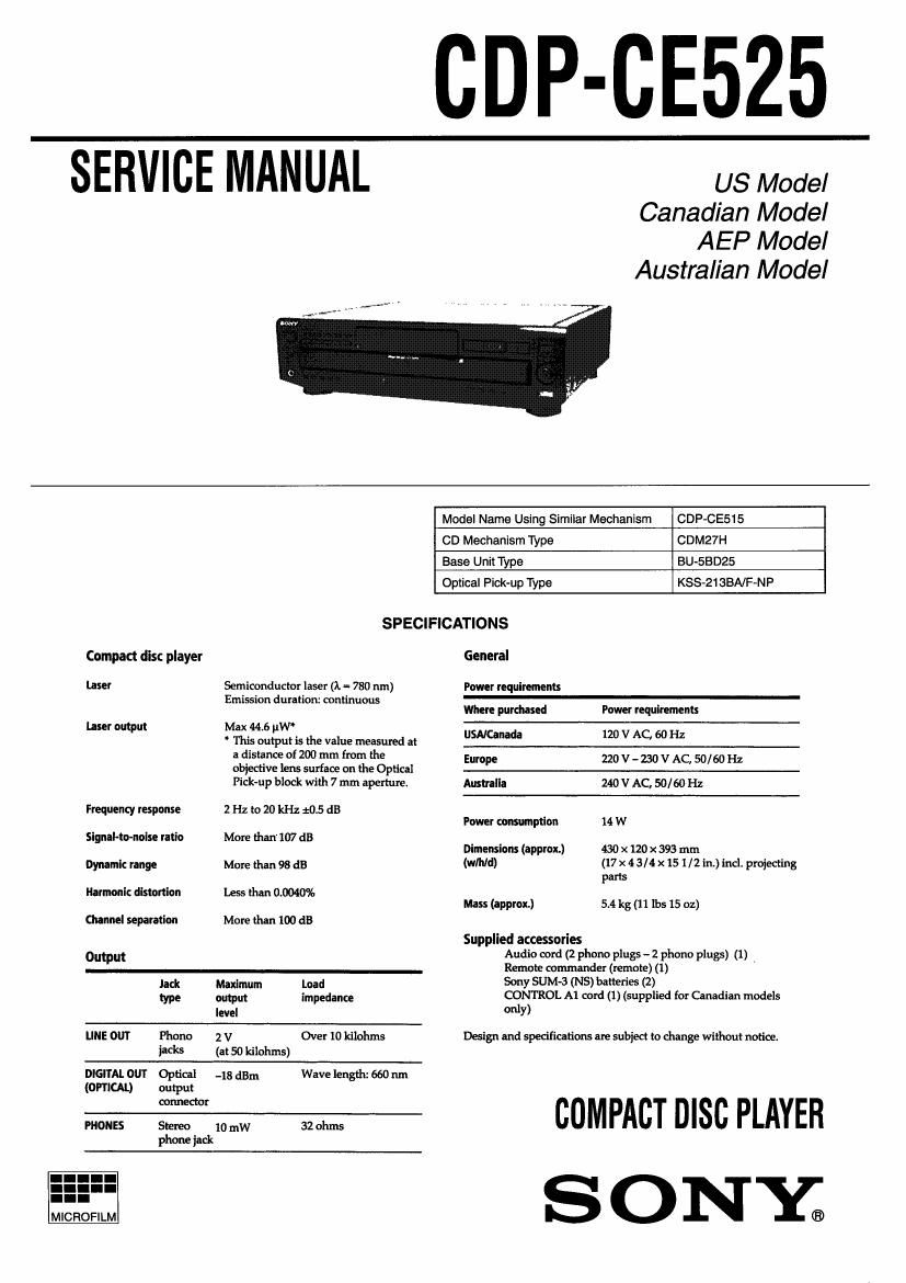
Sony CDP CE525 Service Manual
This is the 40 pages manual for Sony CDP CE525 Service Manual.
Read or download the pdf for free. If you want to contribute, please upload pdfs to audioservicemanuals.wetransfer.com.
Page: 1 / 40