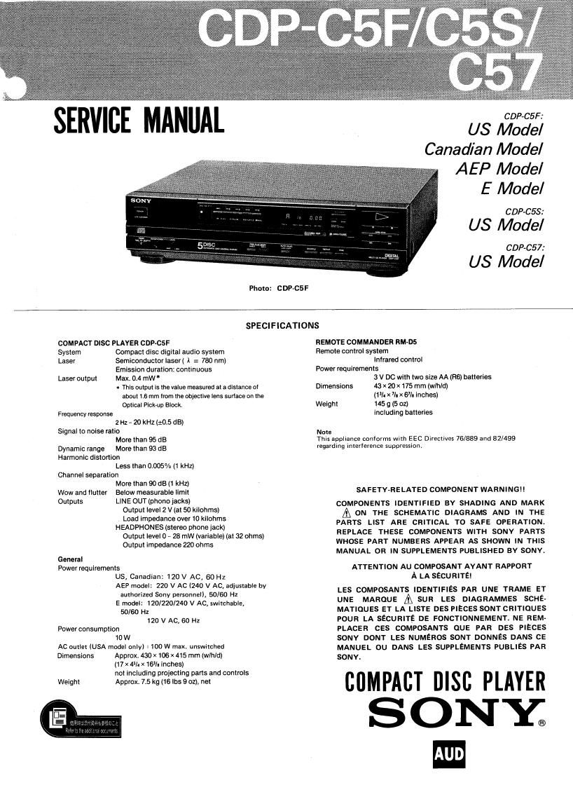
Sony CDP C57 Service Manual

This is the 37 pages manual for Sony CDP C57 Service Manual.
Read or download the pdf for free. If you want to contribute, please mail your pdfs to info@audioservicemanuals.com.

Page: 1 / 37
left right
Sony CDP C57 Service Manual

Extracted text from Sony CDP C57 Service Manual (Ocr-read)


Page 1

SERVICE MAL

Photo: GDP-(25F

GDP-05F:

US Model
Canadian Model

AEP Model
E Model

GDP-05$:

US Model

GDP-05 7:

US Model

SPECIFICATIONS

COMPACT DISC PLAYER CDP-CSF
System Compact disc digital audio system
Laser Semiconductor Iaser( )I = 780 nm)

Emission duration: continuous
Laser output Max. 0.4 mW *
w This output is the value measured at a dlslance of
about 1.6 mm Irom the objective lens surlaoe on the
Optical Pick-up Block.
Frequency response
2 Hz - 20 kHz (10.5 dB)
Signal to noise ratio
More than 95 dB
Dynamic range More than 93 dB
Harmonic distortion
Less than 0.005% 11 kHz)
Channel separation
More than 90 dB (1 kHz)
Wow and Ilutter Below measurable limit
Outputs LINE OUT (phono jacks)
Output level 2 V (at 50 kilohms)
Load impedance over 10 kilohms
HEADPHONES (stereo phone jack)
Output level 0 - 28 mW (variablei (at 32 ohms)
Output impedance 220 ohms

General
Power requirements
US, Canadian: 120 V AC, 60Hz
AEP model: 220 V AC (240 V AC, adjustable by
authorized Sony personnel), 50/60 H1
E model: 120/220/240 V AC, switchable,
50/60 Hz
120 V AC, 50 Hz
Power consumption
10W
AC outlet (USA model only) I 100 W max. unswitched
Dimensions Approx. 430 X 106X 415 mm (wlh/d)
(17 X 4]: X 16% lnchesl
not Including projecting pans and controls
Weight Approx. 7.5 kg (16 lbs 9 oz), net

REMOTE COMMANDER RM-DS
Remote control system
Infrared control
Power requirements
3 V DC with two size AA (FIB) batteries
Dimensions 43 X 20 X 175 mm (wlhld)
(13/. X 7/: X 67/: Inches)
Weight 145 g (5 oz)
including batteries

Note
This appliance conforms with EEC Directives 76/889 and 82/499
regarding interference suppression.

SAFETY~RELATED COMPONENT WARNING

COMPONENTS IDENTIFIED BY SHADING AND MARK

A ON THE SCHEMATIC DIAGRAMS AND IN THE
PARTS LIST ARE CRITICAL TO SAFE OPERATION.
REPLACE THESE COMPONENTS WITH SONV PARTS
WHOSE PART NUMBERS APPEAR AS SHOWN IN THIS
MANUAL OR IN SUPPLEMENTS PUBLISHED BY SONY.

ATTENTION AU COMPOSANT AYANT RAPPORT
A LA SECURITE!

LES COMPOSANTS IDENTIFIES PAR UNE TRAME ET
UNE MAROUE A sun LES DIAGRAMMES SCHE-
MATIOUES ET LA LISTE DES PIECES SONT CRITIQUES
POUR LA SECURITE DE FONCTIONNEMENT. NE REM-
PLACER CES COMPOSANTS QUE PAR DES PIECES
SONY DONT LEs NUMERos SONT DONNES DANS CE
MANUEL 0U DANS LES SUPPLEMENTS PUBLIES PAR
SONY.

cuMPAcI msc PLAYER
SONY.

Page 2

CDP-CSF/CSS/C57

FEATURES

Compact disc player with 5 disc trays
Plays up to 5 discs continuously with its disc compartment
having 5 disc trays (MULTI play).

Direct access to the deslred disc
Any disc in the compartment can be played with the DISC
SELECT button any time you want (MULTI PLAY).

Various lunctlons

c PROGRAM play function for playing up to 32 selections on
any disc in a desired order

ISHUFFLE play function for playing the selections in a
random order

0 Repeat function for normal, PROGRAM and SHUFFLE play
in either SINGLE or MULTI mode

Memory back up

The programmed playback order is retained for
approximately 3 days with the power turned off or with the
disc compartment being opened. This allows you to confirm
the programmed order referring to the disc labels with the
compartment open.

CAUTIONS ABOUT DISCTAB LE

*Do not push the disc-table in or pull it out
forcibly, since the disc-table does not work
without the power switched on.

*Be careful not to disturb the disc-table in
ejecting motion.

If something like a wire or a finger is caught
by the disc-table, depress the OPEN/CLOSE

button as soon as possible, so that the disc-
table will move reversely.

CONTENTS
Section Title Page
SPECIFICATIONS ....................... 1
FEATURES ........................... 2
SAFETY CHECK-OUT (US Model) ............ 2
MODEL IDENTIFICATION ................. 3

SECTIONl OUTLINE
l-l. LOCATION AND FUNCTION OF

CONTROLS .................. 3
1-2. AUTO PAUSE ................ 5-2
NOTES ON HANDLING THE OPTICAL . . . . 7
SECTIONZ DISASSEMBLY ................ 8
SECTION 3 ADJUSTMENTS .............. 9-12
SECTION4 CIRCUIT BOARDS LOCATION ...... 12
SECTION 5 DIAGRAMS
5-1. MOUNTING DIAGRAM ........ 13-14
5-2. SCI-[EMATIC DIAGRAM llllllll 15-16
5-3. MOUNTING DIAGRAM . 17-20
5-4. SCHEMATIC DIAGRAM. 21-25
IC BLOCK DIAGRAMS ............... 27
SEMICONDUCTOR LEAD LAYOUTS ...... 29
SECTION 6 EXPLODED VIEWS AND PARTS
LIST .................... 30-34
SECTION7 ELECTRICAL PARTS LIST ..... 35-40
SECTIONS TROUBLE SHOOTING ........... 40

SAFETY CHECK-OUT (US Model)

After correcting the original service problem,
perform the following safety check before releasing
the set to the customer:

Check the antenna terminals,metal trim, metallized
knobs, screws, and all other exposed metal parts for
AC leakage. Check leakage as described below.

LEAKAGE TEST

The AC leakage from any exposed metal part to
earth ground and from all exposed metal parts to any
exposed metal part having a return to chassis, must
not exceed 0.5 mA (500 microampers). Leakage
current can be measured by any one of three
methods.

1. A commercial leakage tester, such as the
Simpson 229 or RCA WT-540A. Follow the
manufacturers instructions to use these instru-
ments.

2. A batterycperated AC milliammeter, The Data
Precision 245 digital multimeter is suitable for
this job.

3. Measuring the voltage drop across a resistor by
means of a VOM or battery-operated AC volt-
meter. The limit indication is 0.75 V, so
analog meters must have an.aecurate low-
voltage scale. The Simpson 250 and Sanwa
SH-63Trd are examples of a passive VOM that
is suitable. Nearly all battery operated digital
multimeters that have a 2 V AC range are
suitable. (See Fig. A)

Ta Exposed Metal
Part: on Set

AC
0.15"}: grim / voltmeter
(0.75w

.r-

? Earth Ground

Fig. A. Using an AC voltmeter to check AC leakage.

2-