Sony CDP 361 Service Manual

This is the 30 pages manual for Sony CDP 361 Service Manual.
Read or download the pdf for free. If you want to contribute, please mail your pdfs to info@audioservicemanuals.com.

Page: 1 / 30
left right
Sony CDP 361 Service Manual

Extracted text from Sony CDP 361 Service Manual (Ocr-read)


Page 1

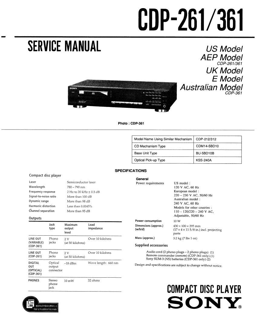
'261/361

SERVICE MANUAL

US Model
AEP Model

CDP~261/361

UK Model
E Model

Australian Model

GDP-36 1

Photo : GDP-361

Compact disc player

Model Name Using Similar Mechanism GDP-212K312

CD Mechanism Type CDM14-EBD10
Base Unit Type BU-SBD1OB
Optical Pick-up Type KSS-240A
SPECIFICATIONS
General

Laser Semiconductor laser
Wavelength 780 - 790 nm
Frequency response 2 Hz to 20 kHz i 0.5 dB
Signal-to-noise ratio More than 100 dB
Dynamic range More than 98 dB
Harmonic distortion Less than 0.0045%
Channel separation More than 95 dB
Outputs

Jack Maximum Load

type output impedance

level

LINE OUT Phone 2 V Over 10 kilohms
(VARlABLE) lacks (a: 50 kilohms)
(CUP-361)
LINE OUT Phone 2 V Over 10 kilohms
(COP-261) jacks (at 50 kilohms)
DlGlTAL Optical _13 dBm Wm'e length: 660 nm
OUT output
(OPTICAL) connector
(CDP-361)
PHONES Stereo 10 mw 32 ohms

phone

jack

US model :

120 V AC. 60 Hz

European model :

220 - 230 V AC 50/60 Hz
Australian model :

240 V AC, 60 Hz

Models for other coutries :

110 «120/220 - 240 V AC»
Adjustable, 50/60 Hz

Power consumption 10 W

430 X 100 x 295 mm
(17 x 4 X 11 5/8 in.) inc], projecting
parts

32 kg (7 lbs 1 oz)

Power requirements

Dimensions (approx)
(wlhld)

Mass (approx.)

Supplied accessories
Audio cord (2 phone plugs - 2 phono plugs) (1)
Remote commander (remote) (CDP-361 only} (1)
Sony SUM-3 (NS) batteries (CDP-SG] only) (2)

Design and specifications are subject to change without notice,

COMPACT msc PLAYER
S 0 NY;

Page 2

SAFETY CH ECK-OUT

After correcting the original service problem, perform
the following safety checks before releasing the set to the
customer:

Check the antenna terminals, metal trim. metallized knobs,
screws, and all other exposed metal parts for AC leakage. Check
leakage as described below.

LEAKAGE

The AC leakage from any exposed metal part to earth
ground and from all exposed metal parts to any exposed metal
part having a return to chassis, must not exceed 0.5 mA (500
microampers). Leakage current can be measured by any one of
three methods.

1. A commercial leakage tester, such as the Simpson 229 or
RCA WT-540A. Follow the manufacturers instructions to
use these instruments.

2. A battery-operated AC milliammeter, The Data Precision
245 digital multimeter is suitable for this job.

3. Measuring the voltage drop across a resistor by means of a
VOM or battery-operated AC voltmeter. The limit
indication is 0.75 V, so analog meters must have an
accurate low»voltage scale. The Simpson 250 and Sanwa
SH-63Trd are examples of a passive VOM that is suitable.
Nearly all battery operated digital multimeters that have a
2V AC range are suitable. (See Fig. A)

To Exposed Metal
Parts on Set

0.15uFE'15kQ
;___.._|

'5 Earth Ground

AC
/ voltmeter
(0.75V)

Fig. A. Using an AC voltmeter to check AC leakage.

SAFETY-RELATED COMPONENT WARNING !!

COMPONENTS IDENTIFIED BY MARK A OR DOTIED

LINE WITH MARK A ON THE SCHEMATIC DIAGRAMS
AND IN THE PARTS LIST ARE CRITICAL TO SAFE

OPERATION. REPLACE THESE COMPONENTS WITH
SONY PARTS WHOSE PART NUMBERS APPEAR AS
SHOWN IN THIS MANUAL OR IN SUPPLEMENTS
PUBLISHED BY SONY.

TABLE OF CONTENTS
Sm M W
1. GENERAL ............................................................... 4
2. DISASSEMBLY

2-1, Front Panel .....
2-2, Base Unit Block .

3. ELECTRICAL BLOCK CHECKING ........................ 6

4. DIAGRAMS
41. 10 Pin Functions

o |C101 Digital Servo Digital Signal Prosessor

(CXD25150)

- l0201 Master


4-2. Block Diagram ...................... 12
4-3. Semiconductor Lead Layouts. 15
4-4. Circuit Boards Location i 15

4-5. Printed Wiring Board
4-6. Schematic Diagram ..

5. EXPLODED VIEWS
5~1. Case Section ..
52. Back Panel Sec IO
53. CD Mechanism Section (CDMl4»5BDlO)
5-4. Base Unit Section (BU~SBD1OB) .............


6. ELECTRICAL PARTS LIST .................................... 27
MODEL IDENTIFICATION
- BACK PANEL -
cm

CDP«261

US Model : 969-747-4El

AEP, East European Model : 969»743»1l:l

German Model : 969-743-9EI
GDP-361

US Model : 969-747-0El

AEP, East European Model : 969-743-OEI
(made in FRANCE)

AEP Model : 969-747-1D
(made in CHINA)

UK Model : 971~521~1El
German Model : 969-743-8El
E Model : 969»747-2I:I
E Model : 969»747-3l:l
(made in CHINA)

Australlan Model : 973-614-0El