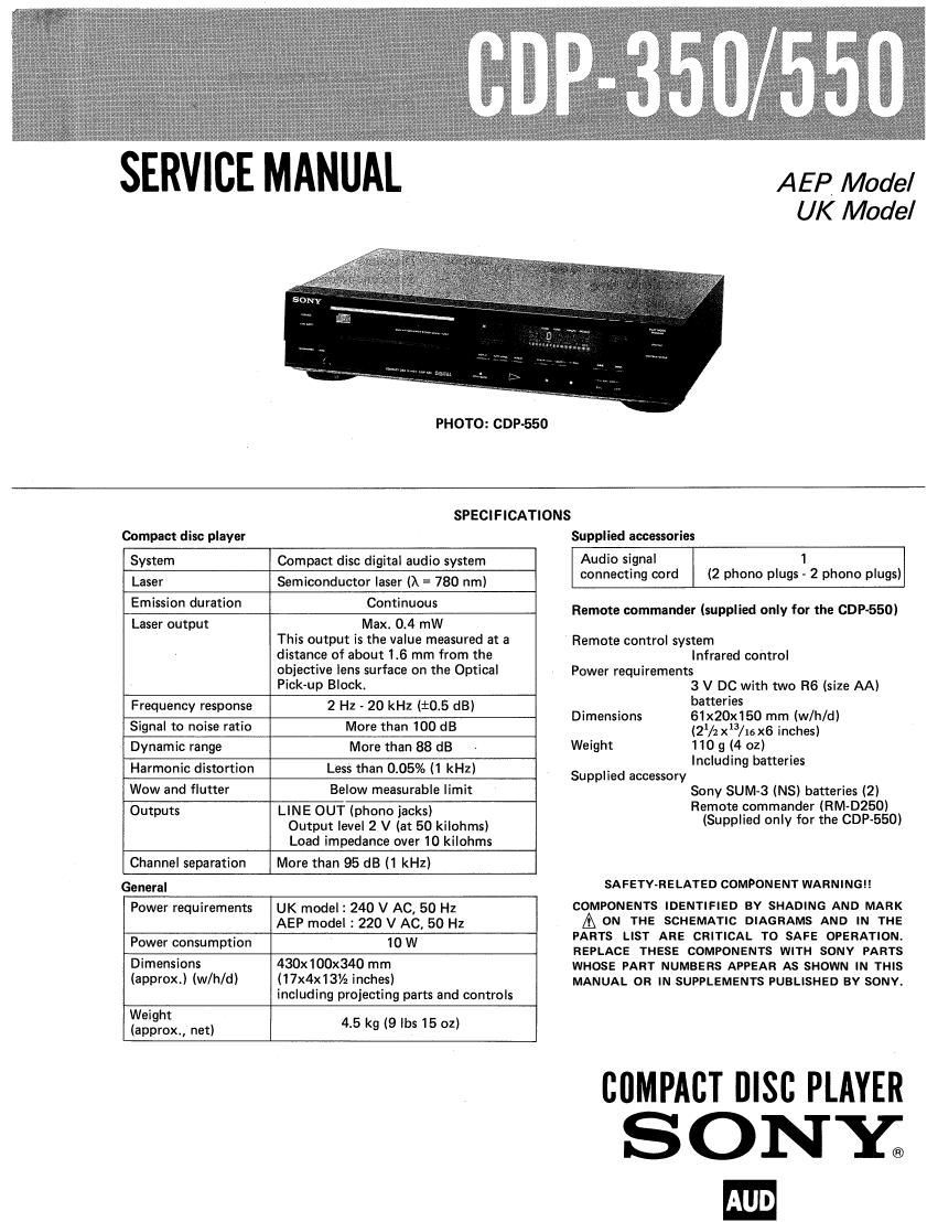
Sony CDP 350 Service Manual

This is the 21 pages manual for Sony CDP 350 Service Manual.
Read or download the pdf for free. If you want to contribute, please mail your pdfs to info@audioservicemanuals.com.

Page: 1 / 21
left right
Sony CDP 350 Service Manual

Extracted text from Sony CDP 350 Service Manual (Ocr-read)


Page 1

SERVICE MANUAL

AEP Model
UK Model

PHOTO: GDP-550

Compact disc player

SPECI FICATIONS

Supplied accessories

System Compact disc digital audio system
Laser Semiconductor laser ()x = 780 nm)
Emission duration Continuous
Laser output Max. 0.4 mW

This output is the value measured at a
distance of about 1.6 mm from the
objective lens surface on the Optical
Pick-up Block.

Frequency response

2 Hz - 20 kHz (10.5 dB)

Signal to noise ratio

More than 100 dB

Dynamic range

More than 88 dB

Harmonic distortion

Less than 0.05% (1 kHz)

Wow and flutter

Below measurable limit

Outputs

LINE OUT (phono jacks)
Output level 2 V (at 50 kilohms)
Load impedance over 10 kilohms

Channel separation

More than 95 dB (1 kHz)

General

Power requirements

UK model: 240 V AC, 50 Hz
AEP model : 220 V AC, 50 HZ

Power consumption

10W

Dimensions
(approx.) (w/h/d)

43Dx100x340 mm
(17x4x13/2 inches)
including projecting parts and controls

Weight
(approx., net)

4.5 kg (9 lbs 15 oz)

Audio signal 1
connecting cord (2 phono plugs - 2 phone plugs)

Remote commander (supplied only for the GDP-550)

Remote control system
Infrared control

Power requirements
3 V DC with two R6 (size AA)
batteries

Dimensions 61x20x150 mm (w/h/d)
(21/2 x3/16 x6 inches)
Weight 110 g (4 oz)

Including batteries
Supplied accessory
Sony SUM-3 (NS) batteries (2)
Remote commander (RM-0250)
(Supplied only for the GDP-550)

SA FETV-RELATED COMPONENT WARNINGI I

COMPONENTS IDENTIFIED BY SHADING AND MARK

A ON THE SCHEMATIC DIAGRAMS AND IN THE
PARTS LIST ARE CRITICAL TO SAFE OPERATION.
REPLACE THESE COMPONENTS WITH SONY PARTS
WHOSE PART NUMBERS APPEAR AS SHOWN IN THIS
MANUAL OR IN SUPPLEMENTS PUBLISHED BV SONY.

COMPACT DISC PLAYER

SONY;
m

Page 2

CDP-350/550

FEATURES TABLE OF CONTENTS
0 Digital filter for high performance and high fidelity. Title Description Page
- PROGRAM play for playing the selections in a desired
order. Specifications ..................... 1
0 SHUFFLE play for playing the selections in a random Features ........................ 2
order. ' Servicing Note .................... 3
- REPEAT function for a single selection, the whole disc, Section 1. Outline
PROGRAM play, or SHUFFLE play. 1-1r Location and Function of Controls ...... 4
' AUTO SPACE function for inserting a blank space of 3 14. Circuit Description ................ 5
seconds between each selection. . .
. . t Section 2. Adjustments ...................... 7
- Easy-to-read display wtndow shows the selection number S t 3 D
being played, all the numbers of the selections on the disc e0 lo" ' 139mm: L L 1 l
the elapsed playing time, and the remaining time. 34' semlco," am ' cad ayout """""
3-2. Mounting Diagram ................. 12
3-3. Schematic Diagram ................ 15
3-4. IC Block Diagram ................. 20
Section 4. Exploded Views and Parts List ......... 23
Section 5. Electrical Parts List ................ 27

0 wow- lit-w-.-lt-n.-lt-lit-l.-¢-

MODEL IDENTIFICATION

-- Specifications Labels -

SONY® MODEL NO, CDP- 350

COMPACT DISC PLAYER

El

SERIAL NO.
MADE IN JAPAN

AEP model: AC: 220V ~ 50/60Hz 10W
UK model : AC: 240V ~ 50/60Hz 10W

-4-.-it-it-.-it-----wow-it»-w---lw-.-l»-.-a-.-»-a---it---ll-t.---,ll-----.ovolit-----.-lt---.t- o-.-porlt-lt-lt-.-l

PROTECTION OF EYES FROM LASER BEAM DURING SERVICING

This set employs a laser. Therefore, be sure to fol- 1. Laser Diode Properties
low carefully the instructions below when servicing. . Material: GaAlAs
O Wavelength: 780 nm
0 Emission Duration: continuous
0 Laser Output: max, 44.6 uW*

CAUTION

* This output is the value measured at a distance of
Use of controls or adiustments 0r performance about 200 mm from the objective lens surface on
of procedures other than those specified herein the Optical Pick-up Blocks

may result in hazardous radiation exposure.

2. During service, do not take the Optical Pick»up
Block apart, and do not adjust the APC circuit.
If there is a breakdown in the APC circuit (includ-
ing laser diode), replace the entire Optiocal Pick-
up Block (including APC borad).