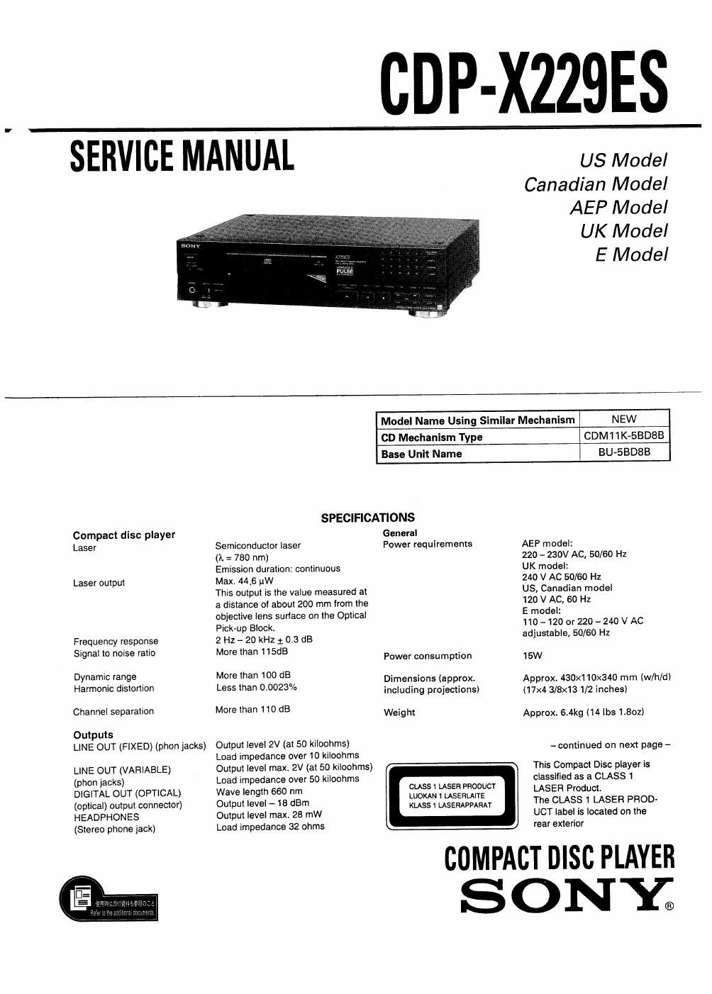
Sony cdp x 229 es service manual

This is the 31 pages manual for sony cdp x 229 es service manual.
Read or download the pdf for free. If you want to contribute, please mail your pdfs to info@audioservicemanuals.com.

Page: 1 / 31
left right
sony cdp x 229 es service manual

Extracted text from sony cdp x 229 es service manual (Ocr-read)


Page 1

CDP-XZZQES

SERVICE MANUAL

US Model
Canadian Model
AEP Model

UK Model

E Model

Model Name Using Similar Mechanism NEW
CD Mechanism Type CDM1 lK-BBDSB
Base Unit Name BU-SBDSB
SPECIFICATIONS
Compact disc player General
Laser Semiconductor laser Power requirements AEP model:
(A = 780 nm) 220 - 230V AC, 50/60 Hz
Emission duration: continuous UK model:
Laser output Max. 44,6 uW 240 V AC 50/60 Hz

This output is the value measured at
a distance of about 200 mm from the
objective lens sudace on the Optical

Pick-up Block
Frequency response 2 Hz - 20 kHz 1 03 dB
Signal to noise ratio More than 115dB ,
Power consumption

Dynamic range More than 100 dB . .

. . D me a .
Harmonic dIslortIon Less than 0.002% igclucfii'ggsréjgggg)
Channel separation More than 110 dB Weight

Outputs
LINE OUT (FIXED) (phon jacks) Output level 2V (at 50 kiloohms)
Load impedance over 10 kiloohms

LINE OUT (VARIABLE) Output level max, 2V (at 50 kiloohms)

(phon jacks) Load impedance over 50 kiloohms

DIGITAL OUT (OPTICAL) Wave length 660 nm (SUI-82,1 3532:5333
(optical) output connector) Output level - 18 dBm KLASS USERAPPAMT
HEADPHONES Output level max, 28 mW

(Stereo phone jack) Load impedance 32 ohms

US, Canadian model

120 V AC, 50 Hz

E model:

110- 120 or 220 -240 V AC
adjustable, 50/60 Hz

15W

Approx. 430x110x340 mm (w/h/d)
(17x4 3/8x13 1/2 inches)

Approx. 6.4kg (14 lbs 1.802)

- continued on next page -

This Compact Disc player Is
classified as a CLASS I
LASER Product.

The CLASS 1 LASER PROD.
UCT label is located on the
rear exterior

COMPACT DISC PLAYER

SONY;

Page 2

CDP-X229ES

Remote commander
Remote control system
Power requirements

Infrared control
3 V DC with two batteries size AA
(IEC designation R6),

Dimensions Approx. 62 x 18 x 175 mm (w/h/d)
(2 1/2 x 23/32 x 7 inches)
Weight Approx. 130 g (4.6 oz)

Including batteries

Design and specifications are subject to change without notice

SAFETY-RELATED COMPONENT WARNINGII

COMPONENTS IDENTIFIED BY MARK A OR DOTTED LINE
WITH MARK A ON THE SCHEMATIC DIAGRAMS AND IN
THE PARTS LIST ARE CRITICAL TO SAFE OPERATION. REPLACE
THESE COMPONENTS WITH SONY PARTS WHOSE PART
NUMBERS APPEAR AS SHOWN IN THIS MANUAL OR IN
SUPPLEMENTS PUBLISHED BY SONY.

ATTENTION AU COMPOSANT AYANT RAPPORT
A LA SECURITEI

LES COMPOSANTS IDENTIFIES PAR UNE MARouE A: SUR
LEs DIAGRAMMES SCHEMATIQUES ET LA LISTE DES PIECES
SONT CRITIQUES POUR LA SECURITE DE FONCTIONNE-
MENT. NE REMPLACER CES COMPOSANTS OUE PAR DES
PIECES SONY DONT LES NUMERos SONT DONNES DANS
CE MANUEL 0U DANS LES SUPPLEMENTS PUBLIE'S PAR
SONY.

TABLE OF CONTENTS
5mm Ifllfl flage
2. ELECTRICAL BLOCK CHECKING 6
3. DIAGRAMS
3-1. Circuit Boards Location .................................. 8
3-2. Semiconductor Lead Layouts ......................... 9
3-3. Block Diagram ........................ . ....................... 10
3-4. Printed Wiring Boards ..................................... 13
3-5. Schematic Diagram ........................................ 17
3-6. IC Pin Functions ............................................. 24
3-7. Waveforms ..................................................... 26
4. EXPLODED VIEWS
4-1. Cabinet Section .............................................. 28
4-2L Front Panel Section 29
4-3. Chassis Section .............................................. 30
4-4. CD Mechanism Section .................................. 31
4-5. Optical Pick-up Block Section ........................ 32

7. ELECTRICAL PARTS LIST 33