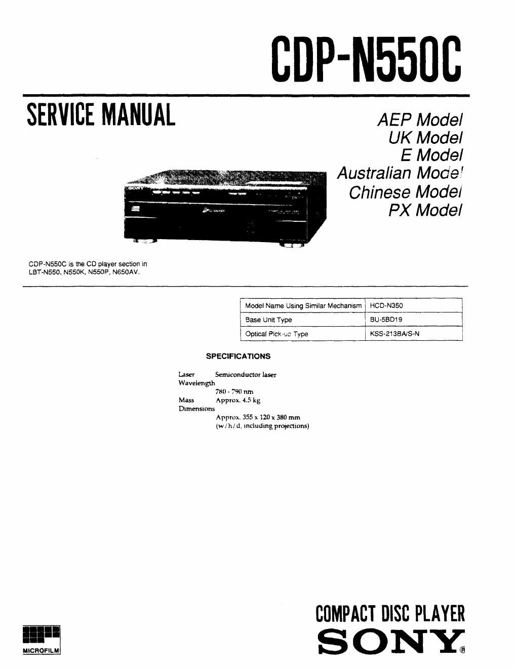
Sony cdp n550c

This is the 17 pages manual for sony cdp n550c.
Read or download the pdf for free. If you want to contribute, please mail your pdfs to info@audioservicemanuals.com.

Page: 1 / 17
left right
sony cdp n550c

Extracted text from sony cdp n550c (Ocr-read)


Page 2

Laser component in this product is capable ol emitting radiation
exceeding the limit for Class 1,

_.__fi

This appliance is classified as a
CLASS l LASER product.

The CLASS 1 LASER PRODUCT
MARKING is located on the rear
exterior.

QASS I LASER PRODUCT
LUOKAN I WERLAITE
N55 I LASERAPPARAT

This
label is located
inside the unit.

l . Humumums
VARO mummtmmim

_" -_" WE '-
VAFINING '33M. Hagen-rm

my; , ; umuo ulimm m mm mu
E unmet swam so. mu

CAUTION

Use of controls or adjustments or performance of
procedures other than those specified herein may result in
hazardous radiation exposure.

Notes on chip component replacement

- Never reuse a disconnected chip component,

~ Notice that the minus side of a tantalum capacitor may be
damaged by hear.

Flexible Circuit Board Repairing

- Keep the temperature of the soldering iron around 270 C
during repairing

- Do not touch the soldering iron on the same conductor ofthe
circuit board (within 3 times).

0 Be careful not to apply force on the conductor when soldering
or unsoldering,

SAFETY-RELATED COMPONENT WARNING !!

COMPONENTS IDENTIFIED BY MARK A OR DOTTED

LINE WITH MARK A ON THE SCHEMATIC DIAGRAMS
AND IN THE PARTS LIST ARE CRiTICAL TO SAFE

OPERATION. REPLACE THESE COMPONENTS WITH
SONY PARTS WHOSE PART NUMBERS APPEAR AS
SHOWN IN THIS MANUAL OR IN SUPPLEMENTS
PUBLISHED BY SONY.

TABLE OF CONTENTS

Section litLe Ease
SERVICE NOTE .............................................................. 2
1, GENERAL ............................................................... 4
2. DISASSEMBLY

24. Case, Bottom Plate and Front Panel . . 5
2-2. Back Panel and Disc Table A 5
2-3. Bracket (30) ASSY ........... . 6
2-4. Loading Motor Board .................................. . 6
3. ELECTRICAL ADJUSTMENTS .............................. 7

4. DIAGRAMS
4-1. Circuit Boards Location.
4-2. to Block Diagram ........
4-3. Printed Wiring Board - BD Section -
4-4. Schematic Diagram - BD Section -
4-5. Schematic Diagram - Main Section -
4-6. Printed Wiring Board - Main Section -
4-7. IC Pin Functions

~ ICBOi System Control, FL Driver (uFD78044AGF) ....22


5. EXPLODED VIEWS

5-1. Case and Front Panel Section
5-2. Disc Table Section .
5-3. Chassis Section ..
5-4. Base Unit Section (BU-SBD19)


8. ELECTRICAL PARTS LIST .................................... 28

SERVICE NOTE

How to confirm the operation with a single unit

- Normally, this set does not operate with a single unit.
The exclusive jig (J~2501-081-A) is necessary to operate the
set with a single unit.
The cable attached to set is used for connecting with the jig.

How to turn the power on

- If the power switch of the service box is set to ON, the power
supply of the set is turned on. The sound signal is input/
output through CN204 (SYSTEM CONTROL l). in case of
using the input/output terminal of SERVICE BOX, press
Ema button, button and El button for more than

three seconds at once.

NEW LIBERTY

30-1, 302
IN OUT SW

oo oo .4 3

SERVICE
BOX m
/ CN901
1 7P
C DP-NSSOC