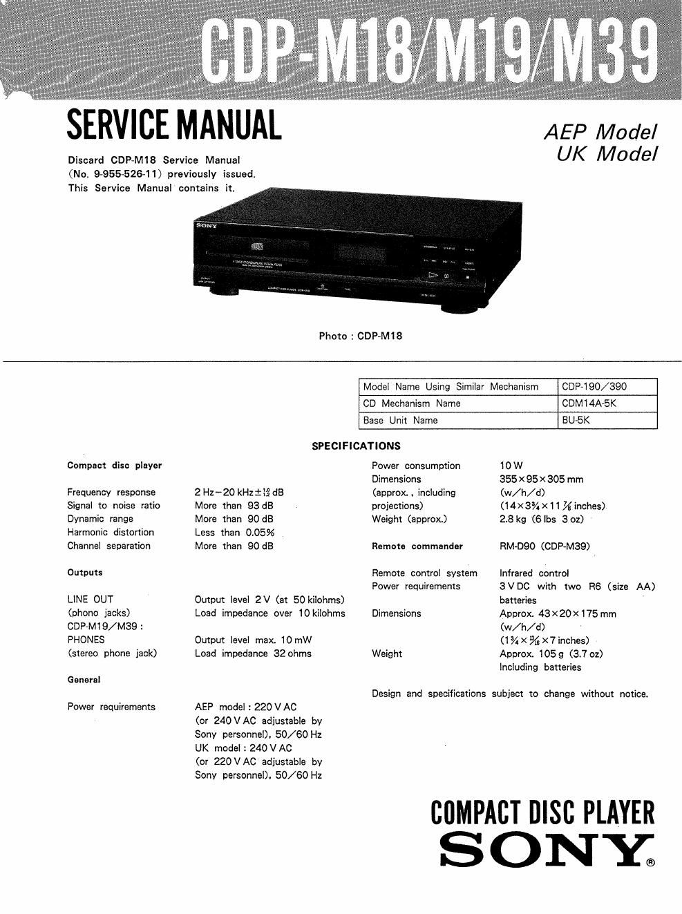
Sony cdp m18 cdp m19 sony m39

This is the 32 pages manual for sony cdp m18 cdp m19 sony m39.
Read or download the pdf for free. If you want to contribute, please mail your pdfs to info@audioservicemanuals.com.

Page: 1 / 32
left right
sony cdp m18 cdp m19 sony m39

Extracted text from sony cdp m18 cdp m19 sony m39 (Ocr-read)


Page 1

SERVICE MANUAL AEP Model

Discard CDP-M18 Service Manual UK MOdE/

(No. 9-955-526-11) previously issued.
This Service Manual contains it.

Photo : GDP-M18

Model Name Using Similar Mechanism CDP-iQO/SQO

CD Mechanism Name CDMl4A-5K
Base Unit Name BU-5K
SPECIFICATIONS

Compact disc player Power consumption 10W

Dimensions 355 X 95 X 305 mm
Frequency response 2Hz-20 kHzii£ dB (approx. , including (w/ h/ d)
Signal to noise ratio More than 93 dB projections) (14X3%X11% inches)
Dynamic range More than 90 dB Weight (approx) 28 kg (6le 3oz)
Harmonic distortion Less than 0.05%
Channel separation More than 90 dB Remote commander RM-D90 (GDP-M39)
Outputs Remote control system Infrared control

Power requirements 3VDC with two R6 (size AA)
LINE OUT Output level 2V (at 50 kilohms) batteries
(phono jacks) Load impedance over 10 kilohms Dimensions Approx 43X20><175 mm
CDP~M1 9/ M39 2 (w/ h/ d)
PHONES Output level max. 10 mW (1%X%X7inches)
(stereo phone jack) Load impedance 32 ohms Weight Approx. 1059 (3.7 oz)

Including batteries

General

Design and specifications subject to change without notice.
Power requirements AEP model : 220VAC

(or 240VAC adjustable by
Sony personnel). 50/60 Hz
UK model : 24OVAC

(or 220 VAC adjustable by
Sony personnel). 50/60 Hz

comer nlsc PLAYER
SONY;

Page 2

CDP-M18/M19/M39

TABLE OF CONTENTS How To OPEN THE DISC TRAY WHEN
POWER swrcH TURNS OFF


Section Title Page
SECTION 1. GENERAL
l-ll Location and Function 0! Controls ~~~~~~~~~~~~~ 4
SECTION 2. DISASSEMBLY .................................... 5
SECTION 3. ELECTRICAL ADJUSTMENTS ---------- 6 /{
fv\ \
SECTION 4. DIAGRAMS K\\~\\\:\~_
4-1. Printed Wiring Boards ~8 l\\\ ..
4-2. Schematic Diagram~~ -11 \b/

4_3. IC Block Diagram ............................ ....15
Turn in the direction
SECTION 5 EXPLODED VIEWS ............................ 17 o of the arrow.
SECTION 6. ELECTRICAL PARTS LIST ~~~~~~~~~~~~~~ 21
SUPPLEMENT-1 |
Caution:When you work. keep the set horizontal.
CDP-M18
M°°EL 'DENT'F'CAT'ON CDP~M19 NOTES ON HANDLING THE OPTICAL PICK-
-Specification Labels- CDP-M39 up BLOCK on BASE UNIT
The laser diode in the Optical pick-up block may
SONYO MODEL NQM suffer electrostatic breakdown because of the poten-
- "- ' tial difference generated by the charged electrostatic
COMPACT DISC PLAYER load, etc. on clothing and the human body.
During repair, pay attention to electrostatic break-
down and also use the procedure in the printed
matter which is included in the repair parts.
The flexible board is easily damaged and should be
SERIAL NO. handled With Care.
MADE lN FRANCE
NOTES ON LASER DIODE EMISSION CHECK
AEP model :AC 220V~50/60Hz The laser beam on this model is concentrated so
UK model 2 AC 240V~50/60HZ as to be focused on the disc reflective surface by the

objective lens in the optical pick-up block. There-
fore, when checking the laser diode emission, observe
more than 25 cm away from the objective lens.

SAFETY-RELATED COMPONENT WARNING"

COMPONENTS IDENTIFIED BY MARK A 08 DOTTED
LINE WITH MARK A ON THE SCHEMATIC DIAGRAMS
AND IN THE PARTS LIST ARE CRITICAL T0 SAFE
OPERATION. REPLACE THESE COMPONENTS WITH
SONY PARTS WHOSE PART NUMBERSAPPEAR AS
SHOWN IN THIS MANUAL OR IN SUPPLEMENTS PUB-
LISHED BY SONY.

_2~