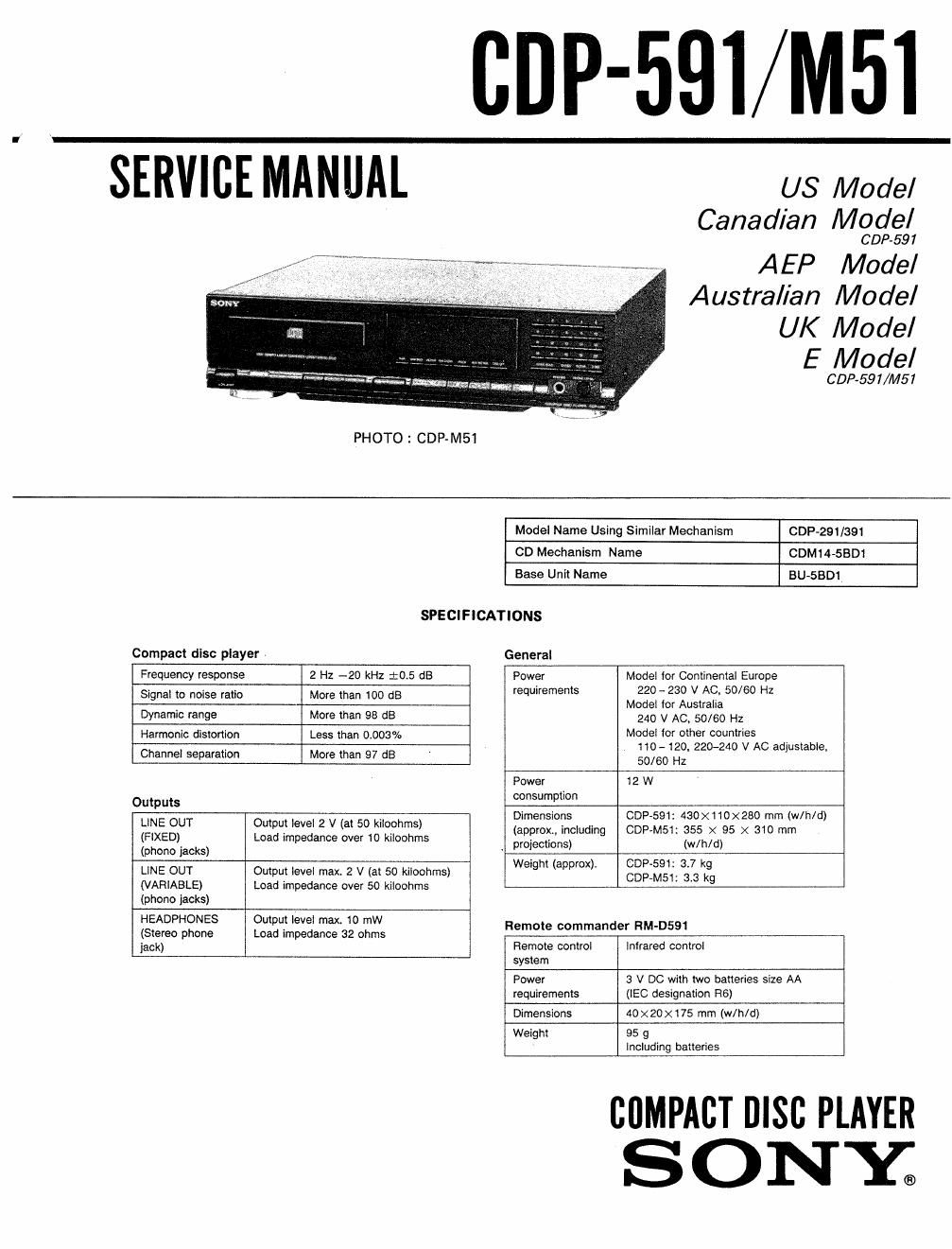
Sony cdp m 51 service manual

This is the 25 pages manual for sony cdp m 51 service manual.
Read or download the pdf for free. If you want to contribute, please mail your pdfs to info@audioservicemanuals.com.

Page: 1 / 25
left right
sony cdp m 51 service manual

Extracted text from sony cdp m 51 service manual (Ocr-read)


Page 2

CDP 91/Wl51

TABLE OF CONTENTS
Supplied accessories _Section Title Pa 9
Connecting cord 1
1. GENERAL
H I
(2 9mm plugs 2 phono p 95) 1-1. Location and Function of Controls ---------- --------- ~ 5
Remote 1
commander 2_ DISASSEMBLY ................... ..................... . ...... 5'
R6 (Size AA) 2
b ll
a eries 3. [0101 (CXA1372Q) PIN FUNCTION---~~~~~-~-~w-~-~~ 7
Design and specifications subject to change without notice, 4' ELECTRICAL BLOCK CHECKING .............. ''''' 8

5. DIAGRAMS
0 IC Block Diagrams ...... ..

Laser component in this product is capable of emitting 1i


, i ; i i 0 Circuit Board Locations 13

radiation exceeding the limit for Class 1 . Semiconductor Lead Layous . 13

0 Printed Wiring Boards ~~~~~~~~~~ .. 15

Note . Schematic Diagrams ................... ............ 19
This appliance conforms with ElEC Directive 87/308/EEC 6. EXPLODED VIEWS

regarding interference suppressnon. (1) Overall Assembly (GDP-591) 22

i . (2) Overall Assembly (CDP-M51)~-~ 23

ggjeffggzgggc (3) MD Block Assembly (CDM14-SBDI) ~ 24

CLASS 1 LASER PRODUCT as a CLASS 1 (4) Optical Block Assembly (BU-5801)- 25

LUOKAN 1 LASERLATE LASER product. 7_ ELECTRICAL PARTS LIST ...................... . ............ 26

KLASS 1 LASERAPPARAT The CLASS 1
LASER PRODUCT
label is located on

the rear exterior. HOW TO OPEN THE DISC TRAY WHEN
POWER SWTCH TURNS OFF

0 Turn in the direction
of the arrow.

Caution : When you work. keep the set horizontal.

SAFETY-RELATED COMPONENT WARNlNGH ATTENT'ON AUFOMPQSANT {WANT RAPPORT
A on DO ED A LA SECURITE!

COMPONENTS IDENTIFIED av MARK TT .

LINE WITH MARK A ON THE scHEMATIc DlAGRAMS LES °°MP°SANTS 'DENT'F'ES PAR NE MARQUE A
AND IN THE PARTS LIST ARE CRITICAL To SAFE sun LE_s DIAGRAMMES SCHEMATIQUES ET LA LiSTE
OPERATION. REPLACE THESE COMPONENTS WITH DES 5°55 30" CR'T'OUES WU LA SECUR'TE
SONY PARTS WHOSE PART NUMBERS APPEAR As DE F°°7'°NNEMENT' E.MPLACER 9 CON
SHOWN IN THIS MANUAL on m SUPPLEMENTS PUB- SAWS °UE PA 3 5° 50' 00" LES
SHED BY sowv. NUMEROS SONT DONNES DANS CE MANUEL ou

DANS LES SUPPLEMENTS PUBLIES PAR SONY.