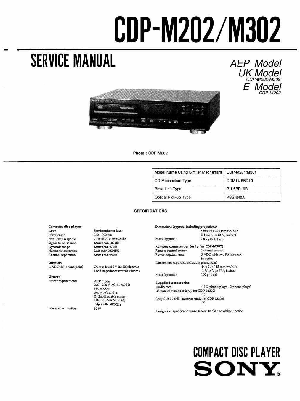
Sony cdp m 202 service manual

This is the 22 pages manual for sony cdp m 202 service manual.
Read or download the pdf for free. If you want to contribute, please mail your pdfs to info@audioservicemanuals.com.

Page: 1 / 22
left right
sony cdp m 202 service manual

Extracted text from sony cdp m 202 service manual (Ocr-read)


Page 2

Laser component in this product is capable of emitting radiation
exceeding the limit for Class I.

This appliance is classified as a
CLASS I LASER product. The
CLASS I LASER PRODUCT

CLASS 1 LASER PRODUCT
LUOKANt LASERLAFTE

KLASSi LASERAPPARAT

exterior.

The following caution label is located inside of the unit.

CAUTION : Mamet: LASER mutton wen elm.
Avon aoosuns 10 mean
, usmua wensmm vec m N
ADVARSEL ' memosaranrven: an we AF Mm.
woe-mos mu: Von swam
VAROI ; AVATIAESSAJA smut-M Wm
mar mum wanuruvu;
VARNING : LASERSYRALING mu: osmu ca. norm»:
o<>< suns" An clue-Mn
ADVARSEL ; u-SYNLIG LASERsrRALwa NA! DEKSEL APNES
mm enmsnwe son ttMLEx.

Use of controls or adjustments or performance of
procedures other than those specified herein may result in
hazardous radiation exposure.

MODEL IDENTIFICATION
- Specification Label -

CDP-M202
CDP-M302

SONY MODEL NO- WM

COMPACT DISC PLAYER

AEP, German model : A0220 - 230V ~ 50/60Hz, 10W

UK model

: A0240 ~ 50/60Hz

MARKING is located on the rear

TABLE OF CONTENTS

Section I1 e Rage
1. SERVICING NOTE ................................................. a
2. GENERAL ............................................................... 4
3. ELECTRICAL BLOCK CHECKING ........................ 5
4. DIAGRAMS
4-1. Block Diagram ........... i 7
4-2, Circuit Boards Location . 9
4-3. Printed Wirlng Boards
4-4, Schematic Diagram
45. IC Block Diagrams.
4-6. Semiconductor Lead Layouts ........
4-7. IC Pin Functions

- ICIO1 Digital Servo & DSP (CXDZS1SQ) .

- |0201 Master Control (CXP82316-037Q) .
5. EXPLODED VIEWS
5-1. Cabinet Section ................................................................ 23
5-2. CD Mechanism Section (CDM14-SBD10)...
543. Optical Pick-up Block Section (BU-SBD1OB) .
6. ELECTRICAL PARTS LIST .................................... 26

E, Saudi Arabia model: A0110 - 120/220 - 240V ~ 50/60Hz. 10W

Notes on chip component replacement

Never reuse a disconnected chip component.

Notice that the minus side of a tantalum capacitor may be

damaged by heat.

Flexible Circuit Board Repairing
Keep the temperature of the soldering iron around 270 °C during

0

repairing

Do not touch the soldering iron on the same conductor of the

circuit board (within 3 times).

SAFETY-RELATED COMPONENT WARNING I!

COMPONENTS IDENTIFIED BY MARK A OR DOTTED
LINE WITH MARK A ON THE SCHEMATIC DIAGRAMS

AND IN THE PARTS LIST ARE CRITICAL TO SAFE

OPERATION. REPLACE THESE COMPONENTS WITH

Be careful not to apply force on the conductor when soldering or

unsoldering.

SONV PARTS WHOSE PART NUMBERS APPEAR AS
SHOWN IN THIS MANUAL OR IN SUPPLEMENTS
PUBLISHED BY SONY.