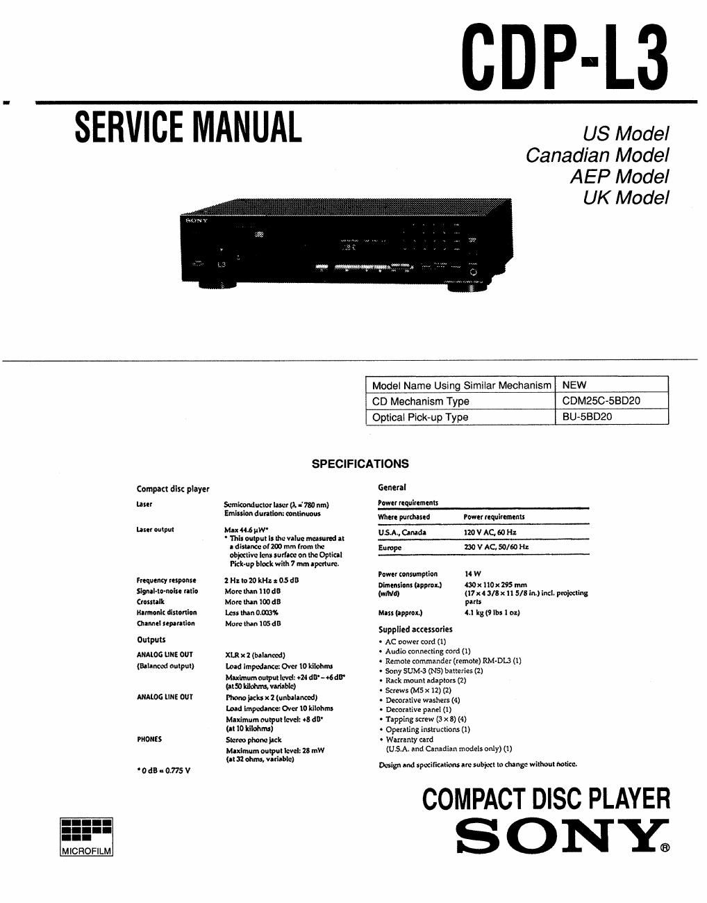
Sony cdp l 3 service manual

This is the 31 pages manual for sony cdp l 3 service manual.
Read or download the pdf for free. If you want to contribute, please mail your pdfs to info@audioservicemanuals.com.

Page: 1 / 31
left right
sony cdp l 3 service manual

Extracted text from sony cdp l 3 service manual (Ocr-read)


Page 1

SERVICE MANUAL

CDP-L3

US Model
Canadian Model
AEP Model

UK Model

Compact dis: playev
but

lam output

fuquency response
mammals. ratio
(mutant

umnonk distonion
anneal sepataflon
Outputs

ANALOG KIN! 00!
(Balanced oulpul)

ANALOG LINE OUT

PHONES

'0dB-0.775V

Model Name Using Simiiar Mechanism NEW
CD Mechanism Type CDMQSC-SBDZO
Opticai Pick-up Type BU«SBD20
SPECIFICATIONS
Generai
Serukomluctor laser (1 -' 790 um) Pom! nquimnent;
Emissmn duration: munm Where wronged Power requiumenx:
Max .6 gm-
- This output I: lhu value 4 at 5" an 120 V AC 50 H
I distance cum mm (mm lite Europe no v AC, 50/60 H;
obitxtivc lens sumo: on the Optical
Pick-up blodt with 7 mmnpcnum.
Power tonxumptiou 1 W
1 H lo 20 k: x 05 1 Dlmmsion: (approL) 430x "0x 295 mm
W W 0 Mild) (17x4 alsxn 5131...) Incl. pmiccling
Mm man too an pans
Less than 0,0001 Mass (approx) 4.: kg (9 lbs 1 oz)
More than 105 an .
Supplied attessones
AC power coxd (X)
XLqubalmzcd) ~ Audio connecting cordu)

Laid Impedanw. 04c! 10 kilohnu

Maximum output de1 014 dB- 06dB
(315) kflohns, vuiahtc)

Hm jack x 2 (unbllanced)
Load Impedance: Over to mom;

Maximum output level: 8 dB'
(at 10 ItIIohms)

Siam phone pick

Maximum output level: 15 am
(at :2 ohms, variable)

~ Remote commander (remote) RM-DL'! (i)
. Sony SUM-3 (NS) batteries (2)
- Rack mount adaptors (2)
- Screws (M5 x 12) (2)
- Decorative washers (4)
- Decorative panei (t)
o Tapping screw (3 x 8) (4)
- Opetaiing instructions (1)
- Watranty card
(USA. and Canadian models only) (1)

Design and specifications m: subject m clung: withuut Mticc.

COMPACT DISC PLAYER

SONY;

Page 2

The following caution label is located inside of the unit.

CAUTION ; vastoLE usan ammo» was» arm
%

. USYNLIG ussnsmnma vED AENINE w
ADVARSEL SIKKERNEDSAFBGVDERE ER UDE AF FUNKTTDN,
w
WHO, ; Avmrsssr n SUOMLUKIYUS own-new

mar ALTmNA LASERSATEILVLLE

-. LASERSYRAUNG m DENNA-DEL in 699 ura '
VAHN'NG ocu spins» in maxoPPLAo

~ USYNLIG LASERSVRALING MAR DEKSEL APNES
ADVERSE umaA EKSPoNEPwo roa smALEN.

This appliance is classified
as a CLASS 1 LASER
product.

was I LASERAFPAHAT The CLASS 1 LASER
PRODUCT MARKING is
located on the rear exterior.

CLASS I LASER PRODUCT
LUOKAN I LASERLAITE

CAUTION

Use of controls or adjustments or performance of
procedures other than those specified herein may result in
hazardous radiation exposure.

Notes on chip component replacement

- Never reuse a disconnected chip component.

- Notice that the minus side of a tantalum capacitor may be
damaged by heat.

Flexible Circuit Board Repairing

- Keep the temperature of the soldering iron around 270 °C during
repairing.

v Do not touch the soldering iron on the same conductor of the
circuit board (within 3 times).

~ Be careful not to apply force on the conductor when soldering or
unsoldering.

SAFETY-RELATED COMPONENT WARNING I!

COMPONENTS IDENTIFIED BY MARK A OR DOTTED
LINE WITH MARK A: ON THE SCHEMATIC DIAGRAMS
AND IN THE PARTS LIST ARE CRITICAL TO SAFE
OPERATION. REPLACE THESE COMPONENTS WITH
SONY PARTS WHOSE PART NUMBERS APPEAR AS
SHOWN IN THIS MANUAL OR IN SUPPLEMENTS
PUBLISHED BY SONY.

TABLE OF CONTENTS

§gg1ign Tit e Basie
SECTION 1. SERVICING NOTE ................................. 3
SECTION 2. GENERAL .................................................... 4

SECTION 3. DISASSEMBLY
3- 1. warding Panel ........
3-2. MD (BU~SBD20) Block


SECTION 4. TEST MODE
4-1. AF Mode ..
4-2. ADJ Mode
4-3. CLV-S Mode

SECTION 5. ELECTRICAL BLOCK CHECKING....8
SECTION 6. DIAGRAMS

6-1. Circuit Boards Location
6-2. Printed Wiring Board - BD Section ~
6-3. Schematic Diagram - BD Section -
6-4. Printed Wiring Board - Main Section ~-
6-5. Schematic Diagram - Main Section - ..
66. [C Block Diagrams - BD Section » ..

- Main Section -


6-7. IC Pin Functions

- lClOl Digital Signal Processor (CXD2545Q) .............. 25
- ICSOl CD Mech, Controller, FL Driver
(CXP823l6-063Q) 28

SECTION 7. EXPLODED VIEWS
7»1. Case and Back Panel Section
7-2. Front Panel Section ..............
7-3. Mechanism Deck Section (CDMZSC-SBDZO)
7-4. Base Unit Section (BU-SBDZO) ...................

SECTION 8. ELECTRICAL PARTS LIST ............... 33
MODEL IDENTIFICATION
- BACK PANEL -
W
|_I |_l

US, Canadian model : 4-980-078-1El
AEP, UK model : 4-980-078»2D

ATTENTION Au COMPOSANT AYANT RAPPORT

A LA SECURITEII
LEs COMPOSANTS IDENTIFIES PAR UNE MARGUE A
sun LES DIAGRAMMES SCHEMATIOUES ET LA
LISTE DES PIECES SONT CRITIQUES POUR LA
SECURITE DE FONCTIONNEMENT. NE REMPLACER
CEs COMPOSANTS QUE PAR DES PIECES SONY
DONT LES NUMEROS SONT DONNES DANS CE
MANUEL ou DANS LES SUPPLEMENTS PUBLIES
PAR SONY.

_2__